
Network signal output circuit

An output circuit and network signal technology, applied in the field of network signal output circuit, can solve problems such as timing advance, output too fast, network card chip unable to receive 100MHZ network clock signal normally, etc.

Inactive Publication Date: 2013-06-05
HONG FU JIN PRECISION IND (SHENZHEN) CO LTD +1
View PDF0 Cites 3 Cited by
  • Summary
  • Abstract
  • Description
  • Claims
  • Application Information

AI Technical Summary

Problems solved by technology

The traditional PCH_PWROK signal is usually output too fast and the timing is ahead of other signals, so that the network card chip cannot normally receive the 100MHZ network clock signal when the computer system is powered on and self-tested, and the computer system cannot detect the network after the computer system is turned on.

Method used


Image

  • Network signal output circuit
  • Network signal output circuit

Examples


Embodiment Construction

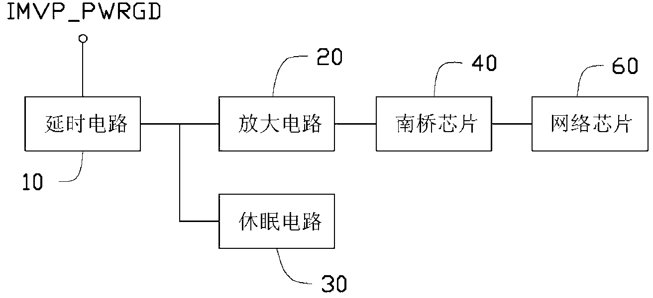
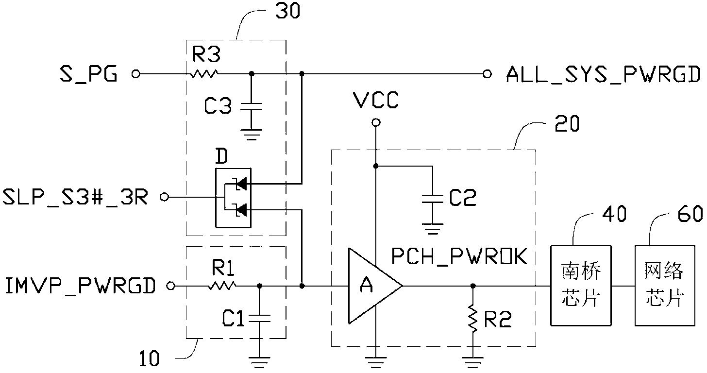
[0011] see figure 1 with figure 2 A preferred embodiment of the network signal output circuit of the present invention includes a delay circuit 10, an amplifying circuit 20 electrically connected to the delay circuit 10, and an amplifying circuit electrically connected to the delay circuit 10 and the amplifying circuit 20. Sleep circuit 30 , a south bridge chip 40 and a network chip 60 . The delay circuit 10 receives a first DC voltage signal, and outputs the first DC voltage signal after a delay. The amplifying circuit 20 receives the delayed first DC voltage signal, converts the delayed first DC voltage signal into a second DC voltage signal, and outputs it to the south bridge chip 40 . The south bridge chip 40 outputs a network clock signal to drive the network chip 60 after receiving the second DC voltage signal. The dormancy circuit 30 receives a system power supply normal signal, and outputs a system dormancy signal to the south bridge chip 40 according to the system...


PUM


Abstract

The invention discloses a network signal output circuit. The network signal output circuit comprises a time-delay circuit, an amplifying circuit, a south bridge chip and a network chip, wherein the amplifying circuit is electrically connected with the time-delay circuit. The time-delay circuit receives a first direct current voltage signal and the time-delay circuit can output the first direct current voltage signal after the first direct current voltage signal is delayed. The amplifying circuit receives the first direct current voltage signal which is output delayed. The amplifying circuit can be converted into the output first direct current voltage signal which is delayed to a second direct current voltage signal so as to output to the south bridge chip. The south bridge chip outputs a network clock signal to drive the network chip after the south bridge chip receives the second direct current voltage signal.

Description

technical field [0001] The invention relates to a signal output circuit, in particular to a network signal output circuit in a computer system. Background technique [0002] The motherboard network card chip refers to the network card chip integrated in the motherboard that integrates network functions. The traditional computer motherboard amplifies the IMVP_PWRGD (central processing unit power supply is normal) signal and then outputs the PCH_PWROK (south bridge chip power supply is normal) signal to drive the south bridge. The chip outputs a 100MHZ network clock signal to the network card chip. The traditional PCH_PWROK signal is usually output too fast and the timing is ahead of other signals, so that the network card chip cannot normally receive the 100MHZ network clock signal when the computer system is powered on and self-tested, and the computer system cannot detect the network after it is turned on. Contents of the invention [0003] In view of the above, it is ne...

Claims


Application Information

Patent Timeline
Patent Type & Authority Applications(China)
IPC IPC(8): G06F1/04
Inventor 胡可友
Owner HONG FU JIN PRECISION IND (SHENZHEN) CO LTD
Learn More