Zero voltage electronic touch switch

A touch switch, zero-voltage technology, applied in electronic switches, electrical components, pulse technology, etc., can solve the problems of electric shock by turning off lights, affecting product exports, and high component costs, achieving high reliability, extended life, and low cost. Effect

Inactive Publication Date: 2015-08-12
CITY COLLEGE WENZHOU UNIV
View PDF4 Cites 0 Cited by
  • Summary
  • Abstract
  • Description
  • Claims
  • Application Information

AI Technical Summary

Problems solved by technology

[0003] The electronic touch switches currently on the market have the following defects: 1. Lack of zero voltage control function. Although some products have zero voltage function in working state, the startup is still random.
This will not only affect the life of the switch and lamps, but also make it difficult to pass the EMC test and affect the export of products; 2. The no-load current of the switch is greater than 100μA, and cold flashes will appear when controlling low-power energy-saving lamps and LED lights; 3. Lack of live wire identification function , the switch is wrongly connected to the ground wire, and there will be a danger of electric shock when the light is turned off for maintenance; 4. The presence of electrolytic capacitors in the circuit affects the working life and long-term reliability; 5. The structure is complex and the cost of components is high
Due to the above reasons, it has seriously affected the popularization and promotion of electronic touch switches.

Method used


Image

  • Zero voltage electronic touch switch
  • Zero voltage electronic touch switch
  • Zero voltage electronic touch switch

Examples


Embodiment 1

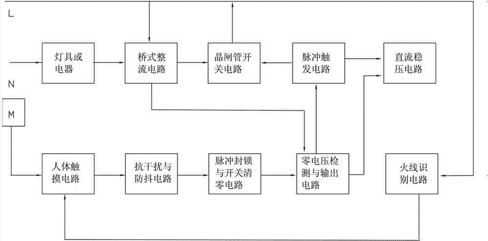
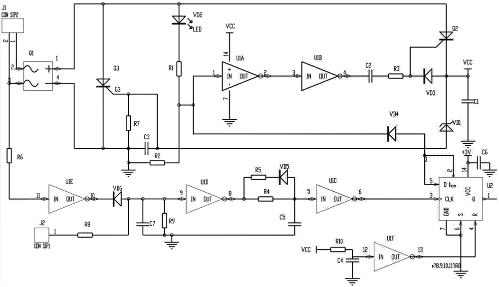
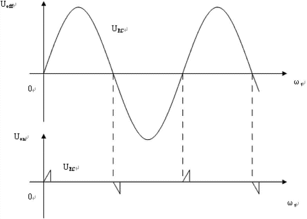
[0017] Such as figure 1 , figure 2 , image 3 As shown, the zero-voltage electronic touch switch of this embodiment includes a bridge rectifier circuit Q1 composed of rectifier elements, a thyristor switch circuit composed of thyristor Q3, a pulse trigger circuit composed of micro-trigger thyristor Q2, zero voltage detection and output Circuit (including zero voltage detection circuit and zero voltage output circuit), human body touch circuit composed of the fourth integrated inverter U1D, pulse blockade and power-on reset circuit, live wire identification circuit and DC voltage regulator circuit. The input end of the thyristor switch circuit is connected to the output end of the bridge rectifier circuit, the control end of the thyristor switch circuit is connected to the trigger signal output end of the pulse trigger circuit, the current output end of the pulse trigger circuit is connected to the input end of the DC voltage regulator circuit, The output end of the human ...

Embodiment 2

[0027] Such as Figure 4 , Figure 5 As shown, Embodiment 2 has a bridge rectifier circuit composed of rectifier element Q1 in Embodiment 1, a switch circuit composed of power thyristor Q3, a pulse trigger circuit composed of micro-trigger thyristor Q2, a zero voltage detection and output circuit, The live wire identification circuit, the human body touch circuit and the DC voltage stabilizing circuit are different in that: the pulse blockade circuit is composed of a monostable circuit composed of the seventh integrated inverter U1G with a delay circuit and the first blockade diode VD4 , the input end of the seventh integrated inverter U1G (the 13th pin of U1G) is connected with the output end (the 8th pin of U1D) of the fourth integrated inverter U1D of the human body touch circuit through the PNP transistor Q4, the seventh integrated The output terminal of the inverter U1G (the 12th pin of U1G) is connected with the input terminal (the 1st pin of U1A) of the first integra...


PUM


Abstract

A no-voltage-type electronic touch switch comprises a bridge rectifier circuit, a switch circuit, a pulse trigger circuit, a pulse inhibiting circuit, a human body touch circuit and a direct-current voltage stabilizing circuit. A non-voltage detection and output circuit is inserted between the pulse trigger circuit and the pulse inhibiting circuit. When the switch is just triggered and turned on or is under a conducting state, the electronic touch switch can guarantee that in any state, the switch is always under ideal conditions including a non-voltage conducting state or under a non-current off state. The electronic touch switch can be used as a wall switch or a remote-control switch or a corridor lamp delay switch.

Description

technical field [0001] The invention relates to an electronic touch switch, which can be used as a wall switch, a remote control switch and a corridor light delay switch. Background technique [0002] The electronic touch switch mainly includes a bridge rectifier circuit, a switch circuit, a pulse trigger circuit, a pulse blockade circuit, a human body touch circuit, and a DC voltage regulator circuit. On-off of load circuits such as electrical appliances. [0003] The electronic touch switches that appear on the market currently have the following defects: 1. Lack of zero-voltage control function. Although some products have a zero-voltage function in the working state, the startup is still random. This will not only affect the life of the switch and lamps, but also make it difficult to pass the EMC test and affect the export of products; 2. The no-load current of the switch is greater than 100μA, and cold flashes will appear when controlling low-power energy-saving lamps ...

Claims


Application Information

Patent Timeline
Patent Type & Authority Patents(China)
IPC IPC(8): H03K17/96
Inventor 刘冰冰刘若望刘希真
Owner CITY COLLEGE WENZHOU UNIV
Why Eureka
Try Eureka