Database system and data synchronization method thereof

A database and data technology, applied in the database field, can solve the problems of prolonged delay, affecting the performance of the host, and unavailability of the replication source, so as to overcome the single source of replication and improve data consistency and performance.

Active Publication Date: 2013-06-05
HUAWEI TECH CO LTD
View PDF3 Cites 10 Cited by
  • Summary
  • Abstract
  • Description
  • Claims
  • Application Information

AI Technical Summary

Problems solved by technology

[0005] The common problem of the above two existing solutions is that if the network between the standby machine and the replication source is unstable, or the replication source is unavailable, the standby machine cannot replicate new data
In addition, when the host is used as a single replication source, its load will be proportional to the number of standby machines, which will affect the performance of the host, and then affect the data consistency and performance of the entire cluster; when setting the standby machine for transfer, the redo log needs to be transferred to be replicated To the leaf standby machine, the delay is prolonged, which will also affect the data consistency and performance of the entire cluster

Method used


Image

  • Database system and data synchronization method thereof
  • Database system and data synchronization method thereof
  • Database system and data synchronization method thereof

Examples


Embodiment 1

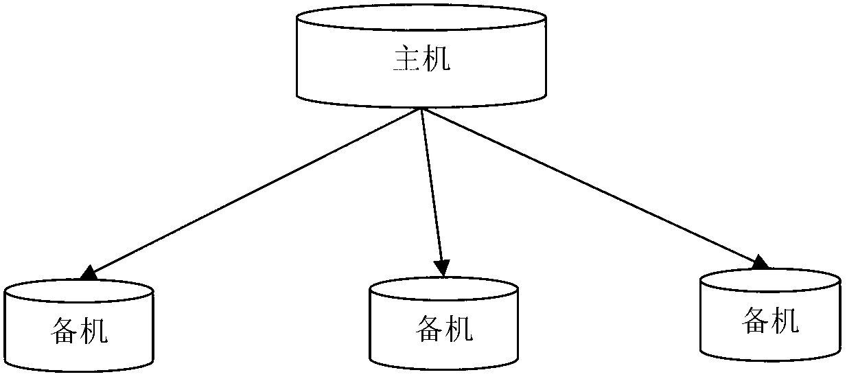
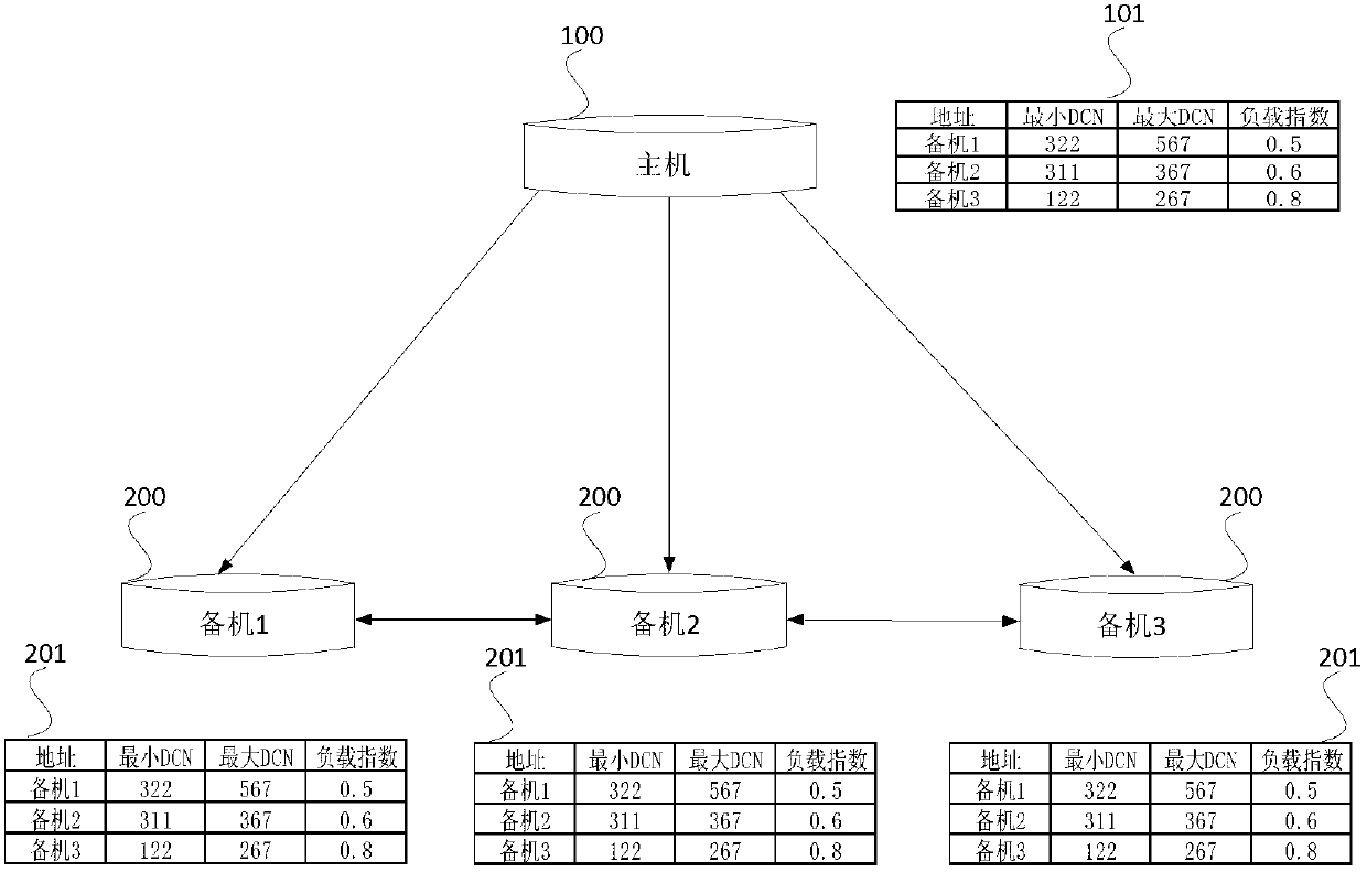
[0054] figure 2 is a schematic diagram of the database system in Embodiment 1 of the present invention, such as figure 2 As shown, the database system includes: a main machine 100 and multiple standby machines 200 connected to the main machine 100 .

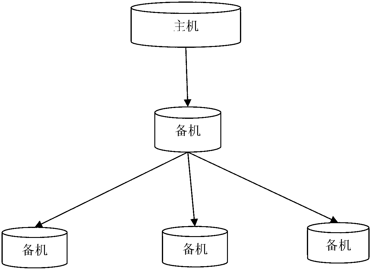
[0055] Wherein, the backup machine 200 is used to copy data from the host machine 100, and when the backup machine 200 cannot copy data from the host machine 100, the backup machine 200 is also used to select and connect to other backup machines according to a predetermined strategy. machine 200, and copy data from the connected standby machine 200.

[0056] A main routing table 101 is maintained on the main machine 100, and the main routing table 101 records an entry corresponding to each of the standby machines. The table entry records the standby machine address of the current standby machine 200, the minimum DCN (Database Change Number, the unique identifier of the database change), and the maximum DCN; in addition, the t...

Embodiment 2

[0089] Figure 4 is a flow chart of the data synchronization method described in Embodiment 2 of the present invention, such as figure 2 As shown, the method comprises the steps of:

[0090] S100: The standby machine establishes a communication connection with the host computer in the database system where it is located.

[0091] S200: When the standby machine cannot copy data from the master machine, the standby machine selects another standby machine connected to the database system according to a predetermined strategy, and copies data from the connected standby machine.

[0092] Wherein, when the following conditions occur in the standby machine, the standby machine determines that it cannot copy data from the main machine itself: the standby machine cannot connect to the main machine; or, the standby machine finds that there is no The data to be replicated; or, the standby machine finds that the load of the main machine has reached a predetermined upper limit.

[0093...


PUM


Abstract

The invention discloses a database system and a data synchronization method thereof and relates to the field of data bases. The database system comprises a host machine and a standby machine which is connected with the host machine, wherein the standby machine is used for copying data from the host machine, and when the standby machine can not copy the data from the host machine, the standby machine is used for selecting other standby machines to connect according to a predetermined strategy and copying the data from connected standby machines. According to the database system and the data synchronization method of the database system, when the host machine can not be directly as a copy source for the standby machine, the standby machine is capable of selecting other suitable standby machines to be as the copy source, so that the defects that in an existing database system, only the host machine is regarded as the copy source, as the result, the copy source is simplex, and data consistency and performance of a whole cluster is poor are overcome. Data consistency and performance of the database system is effectively improved.

Description

technical field [0001] The invention relates to the technical field of databases, in particular to a database system and a data synchronization method thereof. Background technique [0002] Database systems usually use one master and multiple backups to achieve high availability. When the standby machine is established, it first synchronizes all data from the main machine in full, and then incrementally synchronizes the redo logs and plays them back, so that the data on the standby machine and the main machine can be kept consistent; when the main machine has data changes, redo logs will be generated, so the redo logs It can be regarded as a continuous data flow, flowing from the main machine to the standby machine. The starting point required by the standby machine is identified by the redo ID, which is usually called DCN (database change number). Any data change has a unique DCN identifier. The host's redo log has a size limit. As the old redo log will be overwritten, th...

Claims


Application Information

Patent Timeline
Patent Type & Authority Applications(China)
IPC IPC(8): H04L29/08H04L12/757G06F17/30
Inventor 何雄辉谢锐
Owner HUAWEI TECH CO LTD
Why Eureka
Try Eureka