Clutch device

A clutch device and clutch technology, applied in the direction of clutches, friction clutches, fluid-driven clutches, etc., can solve the problems of fixed force influence, lack of structural space for fixed parts, large structural space, etc., and achieve small size, less structural space, The effect of convenient assembly

Inactive Publication Date: 2013-06-05
SCHAEFFLER TECH AG & CO KG
View PDF6 Cites 20 Cited by
  • Summary
  • Abstract
  • Description
  • Claims
  • Application Information

AI Technical Summary

Problems solved by technology

This requires a lot of installation space, so that, for example, the installation space required for fastening parts is missing and alternative fastening methods must be used, but the fastening effect may still be impaired in the event of forces occurring during operation of the clutch unit

Method used


Image

  • Clutch device
  • Clutch device
  • Clutch device

Examples


Embodiment Construction

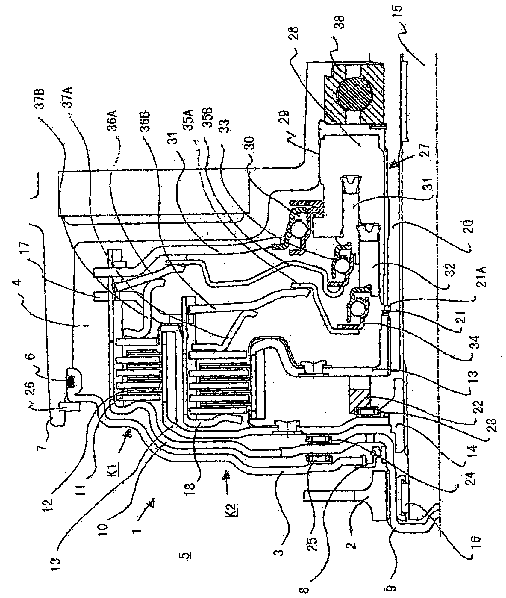
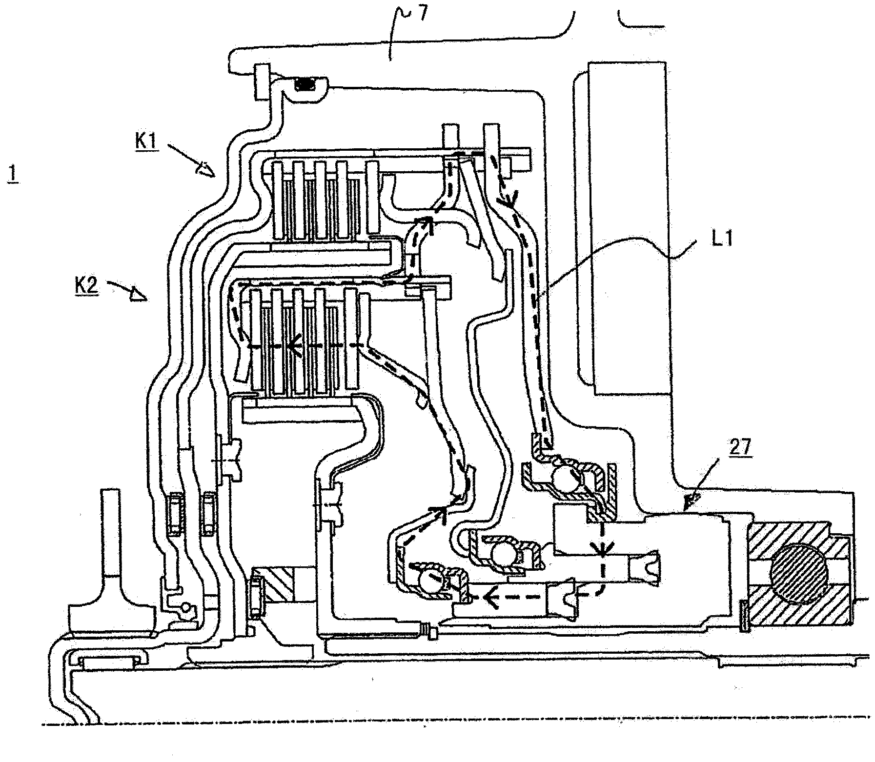
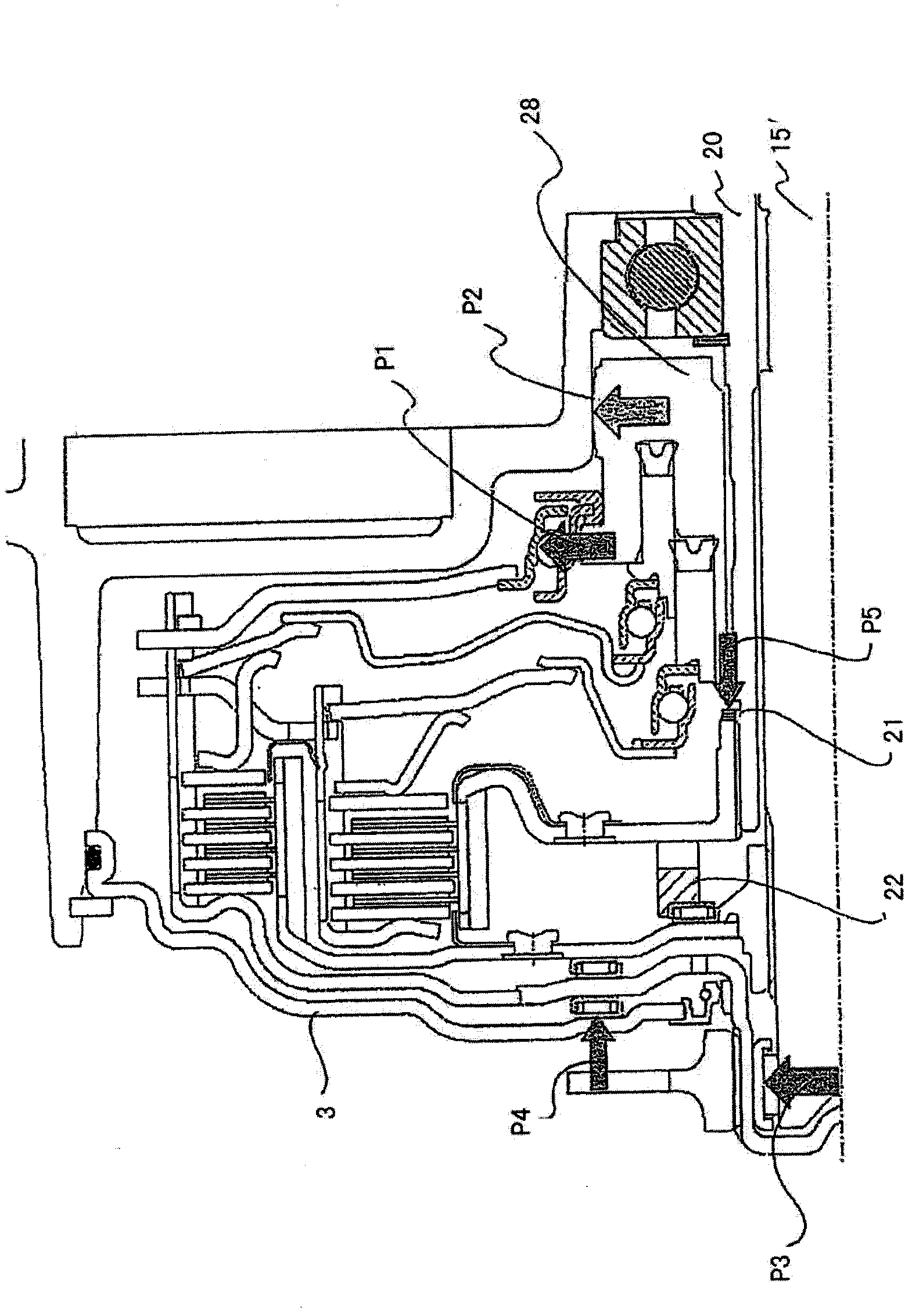
[0032] attached figure 1In the dual clutch 1 formed by two radially nested wet multi-plate clutches K1 and K2 shown, the clutch K1 is arranged radially outside, and the clutch K2 is arranged on the inside. The dual clutch 1 is driven by an output hub 2 of a dual-mass flywheel (not shown separately in the figure, hereinafter also referred to as ZMS) connected in front of the clutch 1 . The clutch cover 3 separating the wet chamber 4 from the dry chamber 5 is located between this dual mass flywheel (ZMS) and the dual clutch 1 . The static seal 6 is preferably realized by means of an O-ring 6 or another static sealing element on the clutch cover 3 towards the transmission housing 7 of the transmission (not shown separately) arranged downstream of the drive train. Sealing towards the dual clutch 1 is preferably effected via a radial shaft sealing ring 8 as dynamic sealing element.

[0033] The output hub 2 of the dual mass flywheel (ZMS) is non-rotatably connected to the clutch ...


PUM


Abstract

A clutch device for a drive train with a drive unit and a transmission arranged downstream has at least one, preferably two multi-plate clutches (k1,k2) which each have an input-side and an output-side plate carrier (701,708) and plates (11,12) alternating in the axial direction. In addition, a restoring spring (713,710) is provided for each multi-plate clutch, for automatically opening the multi-plate clutch, and a tension pot (31) is provided for dissipating the forces which occur when the multi-plate clutch is actuated. The clutch device has a securing ring (722) for axially securing one of the plate carriers relative to the tension pot (31). According to the invention, in an installation position, after the plate carrier which is to be secured has moved relative to the tension pot (31) counter to the spring force of the restoring spring (713,710), the securing ring (722) can be inserted radially from the outside into a retaining groove (720), wherein, in a use position, the securing ring is arranged in a pocket (724) which forms a radially outer stop. As a result, the pocket (724), which is expandable with difficulty under the influence of centrifugal force, can provide a radial stop for the securing ring, which is easily expandable under the influence of centrifugal force, thus permitting a secure fastening of components even when there is little construction space.

Description

technical field [0001] The invention relates to a clutch device, such as a multi-plate clutch device, in particular a wet double clutch, which can be used in a drive train with a drive unit and a transmission arranged downstream of the clutch device, which can be connected to the drive shaft of the drive unit directly or indirectly, and may be housed in a clutch housing that does not rotate with the drive shaft of the drive unit. Background technique [0002] DE 10 2006 049 731 discloses such a wet double clutch in which the clutch is actuated by a lever and the actuation device has a torsion bar which can be actuated electrically or hydraulically. This known dual clutch supports the operating force generated by the operating device through the input side friction plate support, thrust bearing and the clutch cover fixedly connected on the clutch housing. For this reason, the input side friction plate support, thrust bearing and clutch The cover is dimensioned to be heavy an...

Claims


Application Information

Patent Timeline
Patent Type & Authority Applications(China)
IPC IPC(8): F16D21/06F16D25/10
CPCF16D2300/26F16D2300/12F16D13/683Y02T10/76F16D21/06F16D25/10F16D25/087
Inventor D·霍夫施泰特尔O·诺尔J·阿诺尔德
Owner SCHAEFFLER TECH AG & CO KG
Why Eureka
Try Eureka