Air-conditioning ventilation system for rail passenger car and rail passenger car

A technology for ventilation systems and rail passenger cars, which is applied to railway car body parts, railway vehicle heating/cooling, transportation and packaging, etc. It can solve the problems of not being able to adapt to environmental requirements, unreasonable use, and particle blockage of fresh air outlets, so as to avoid frequent Effects of cleaning and replacement, improving wind and sand resistance, and prolonging the replacement cycle

Active Publication Date: 2013-06-12
CRRC TANGSHAN CO LTD
View PDF6 Cites 4 Cited by
  • Summary
  • Abstract
  • Description
  • Claims
  • Application Information

AI Technical Summary

Problems solved by technology

The air duct is installed between the wooden floor and the iron floor, and the roof space inside the car is not used properly; the floor requires high strength, the structure is complicated, the process is difficult, and it is difficult to install; the fresh air outlet is directly installed on the air conditioning unit under the car, and the Sand and particles on the surface are easy to enter the air-conditioning unit, and the anti-wind and sand function is poor. The filter screen needs to be cleaned and replaced frequently.
[0005] However, in West Asia, where the outside air temperature is high and the wind and sand are strong, neither of the above two methods can meet the environmental requirements; the fresh air outlet of the air conditioner unit is easily blocked by wind, sand and particulate matter under the car

Method used


Image

  • Air-conditioning ventilation system for rail passenger car and rail passenger car
  • Air-conditioning ventilation system for rail passenger car and rail passenger car
  • Air-conditioning ventilation system for rail passenger car and rail passenger car

Examples


Embodiment Construction

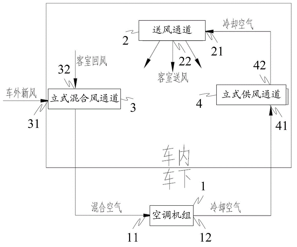
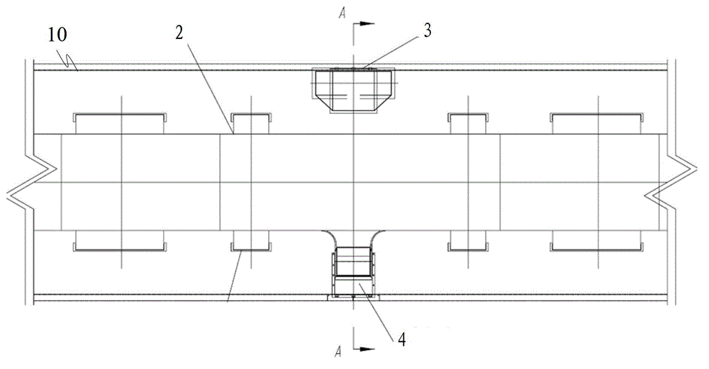
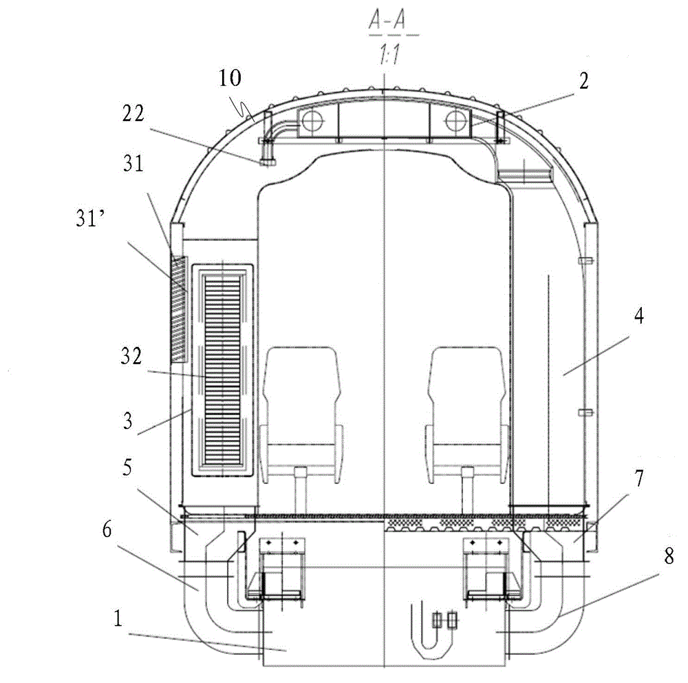
[0014] figure 1 Schematic diagram of the principle of the air-conditioning and ventilation system provided by the embodiment of the present invention; figure 2 The structural representation of the rail passenger car that the embodiment of the present invention provides; image 3 for figure 2 A cross-sectional view along the A-A direction, such as Figure 1-3 As shown, the rail passenger car air conditioning and ventilation system provided by the present invention includes an air conditioning unit 1 arranged under the car and an air supply channel 2 arranged on the roof, and the system also includes a vertical mixed air channel 3 and a vertical air supply Channel 4; the upper part of the vertical mixed air channel 3 is provided with an air inlet 31 communicated with the outside of the car body and a return air port 32 communicated with the inside of the car body, and the lower part of the vertical mixed air channel 3 is communicated with the air conditioning unit 1; the ver...


PUM


Abstract

The invention provides an air-conditioning ventilation system for a rail passenger car and the rail passenger car. The system comprises an air-conditioning unit arranged under the car, an air supplying channel arranged at the car top, a vertical mixed air channel and a vertical air supplying channel, wherein an air inlet communicated with the outside of a car body and an air return port communicated with the inside of the car body are formed in the upper part of the vertical mixed air channel; the lower part of the vertical mixed air channel is communicated with the air-conditioning unit; and two ends of the vertical air supplying channel are communicated with the air supplying channel and the air-conditioning unit respectively. Air outside the car and return air inside the passenger car are mixed in the vertical mixed air channel and then enter the air-conditioning unit to be cooled or heated, and cooled or heated air enters the vertical air supplying channel and finally enters a passenger car room through the air supplying channel at the car top. A fresh air inlet and an air return port of the air-conditioning unit are formed in the vertical mixed air channel, and the vertical mixed air channel can be arranged inside the car, so that blown sand and particulate matters on a rail surface can be prevented from entering the air-conditioning unit, the blown sand resistance of the air ventilation system is improved, washing times of a filter screen are reduced, the replacement period is prolonged, and spaces at the car top and under the car are effectively used.

Description

technical field [0001] The invention relates to ventilation technology, in particular to an air-conditioning ventilation system for a rail passenger car and the rail passenger car. Background technique [0002] At present, there are two air-conditioning and ventilation methods on rail passenger cars, one is the roof air supply type, the air-conditioning unit and air supply channels are located on the roof; the other is the under-vehicle air supply type, the air-conditioning unit and air supply channels are located on the floor Inside. The technical solutions of the above two air supply methods are described in detail below: [0003] Option 1: Roof air supply type, the air conditioning unit must have independent fresh air outlets and return air outlets, the fresh air enters the air conditioning unit from the fresh air outlets at the end or on both sides, and the indoor return air enters the return air outlet of the air conditioning unit through the return air channel. 1. Th...

Claims


Application Information

Patent Timeline
IPC IPC(8): B61D27/00
Inventor 耿亚彬王立航李宝泉欧阳立芝武双虎
Owner CRRC TANGSHAN CO LTD
Why Eureka
Try Eureka