
Auxiliary frame mechanism of automobile

A sub-frame and automobile technology, applied in the substructure, vehicle parts, transportation and packaging, etc., can solve the problems of poor flatness at key installation points, increased labor costs, welding spatter, etc., to improve dimensional accuracy and fatigue life , reduce the risk of torque loosening, and avoid the effect of welding deformation

Active Publication Date: 2013-06-12
ANHUI JIANGHUAI AUTOMOBILE GRP CORP LTD
View PDF6 Cites 10 Cited by
  • Summary
  • Abstract
  • Description
  • Claims
  • Application Information

AI Technical Summary

Problems solved by technology

[0003] The traditional subframe is connected with other parts through welding sleeves. Due to the existence of welding deformation, the dimensional accuracy of the subframe is difficult to control in this structure, resulting in a large installation position of other parts on the subframe. On the other hand, due to the existence of welding heat, the brittleness of sheet metal materials will be strengthened, which will easily lead to material fatigue cracks.
[0004] Due to the application of too many welding processes, the traditional sub-frame will consume more welding materials and increase labor costs
[0005] Due to the large amount of welding at the key installation points of the traditional sub-frame, it is inevitable that there will be welding deformation and welding spatter, resulting in poor flatness at the key installation points, and there will be moments of loosening when assembling parts that bear heavy loads in the later stage Risks, such as the connection between the sub-frame and the body, the connection between the sub-frame and the steering gear, and the connection between the sub-frame and the stabilizer bar, etc., which may cause abnormal noise or even the risk of parts falling off

Method used


Image

  • Auxiliary frame mechanism of automobile
  • Auxiliary frame mechanism of automobile
  • Auxiliary frame mechanism of automobile

Examples


Embodiment

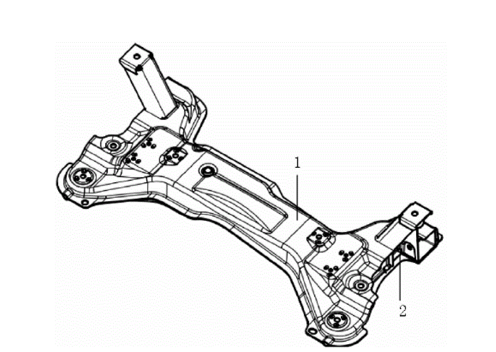
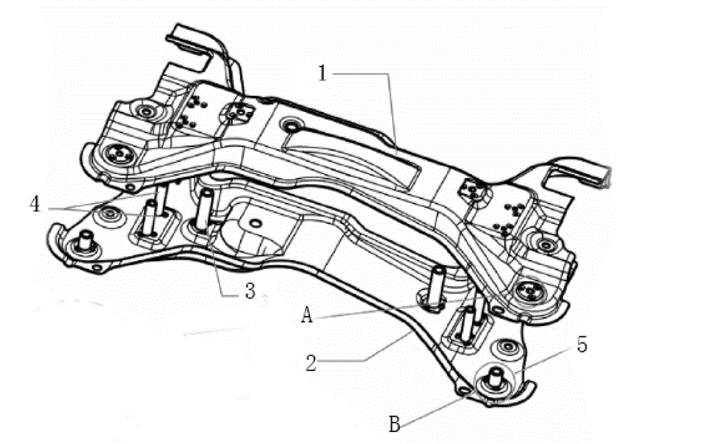
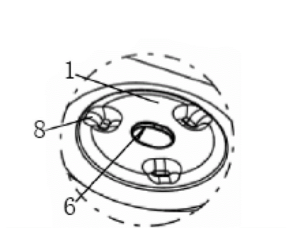
[0045] In the present invention, because the steering gear installation sleeve, the stabilizer bar installation sleeve, and the subframe have the same structure as the limiting bosses in the vehicle body installation sleeve, only the auxiliary frame and the vehicle body installation sleeve among them have the same structure. The structure of the limiting boss is described in detail, and the others are the same as the structure.

[0046] The first mounting hole for the subframe and the body mounting sleeve is arranged on the upper plate of the subframe, and the first mounting hole for the subframe and the body is provided on the lower plate of the subframe corresponding to the first mounting hole for the subframe and the body mounting sleeve. Install the second mounting hole of the sleeve; the surroundings of each mounting hole are stamped and formed three limit bosses at one time, and the number of limit bosses can be changed according to needs, but at least three limit bosses,...


PUM


Abstract

The invention relates to an auxiliary frame mechanism of an automobile, which comprises an auxiliary frame upper plate, an auxiliary frame lower plate, a steering engine mounting sleeve, a stabilizer bar mounting sleeve and an auxiliary frame and automobile body mounting sleeve, wherein both the auxiliary frame upper plate and the auxiliary frame lower plate are provided with steering engine mounting sleeve mounting holes, stabilizer bar mounting sleeve mounting holes and auxiliary frame and automobile body mounting sleeve mounting holes; limiting bosses / a limiting boss protruding towards the auxiliary frame lower plate are / is arranged on the peripheries / periphery of the steering engine mounting sleeve mounting hole and / or the stabilizer bar mounting sleeve mounting hole and / or the auxiliary frame and automobile body mounting sleeve mounting hole of the auxiliary frame upper plate; and limiting bosses / a limiting boss protruding towards the auxiliary frame upper plate are / is arranged on the peripheries / periphery of the steering engine mounting sleeve mounting hole and / or the stabilizer bar mounting sleeve mounting hole and / or the auxiliary frame and automobile body mounting sleeve mounting hole of the auxiliary frame lower plate.

Description

technical field [0001] The invention belongs to the technical field of automobile chassis and chassis, in particular to an automobile front sub-frame mechanism used for connecting a vehicle body. Background technique [0002] As an important load-bearing part of the car, the subframe supports and connects multiple parts of the car, including key components such as the steering mechanism, powertrain, and stabilizer bar assembly. Its fatigue life and dimensional accuracy play a vital role in the safety and performance of the vehicle. [0003] The traditional subframe is connected with other parts through welding sleeves. Due to the existence of welding deformation, the dimensional accuracy of the subframe is difficult to control in this structure, resulting in a large installation position of other parts on the subframe. On the other hand, due to the existence of welding heat, the brittleness of sheet metal materials will be strengthened, which will easily lead to material fa...

Claims


Application Information

Patent Timeline
IPC IPC(8): B62D21/00
Inventor 胡春波李磊杨子平龙道江
Owner ANHUI JIANGHUAI AUTOMOBILE GRP CORP LTD
Learn More