Acoustic logging-while-drilling device and acoustic logging-while-drilling method

A sound wave and well logging technology, applied in the field of applied geophysical well logging, can solve the problems of difficult engineering implementation, large volume, increased power consumption and other problems, and achieve the effect of simple and convenient data processing, high engineering application, and improved signal-to-noise ratio

Inactive Publication Date: 2014-12-03
CHINA UNIV OF PETROLEUM (EAST CHINA)
View PDF6 Cites 3 Cited by
  • Summary
  • Abstract
  • Description
  • Claims
  • Application Information

AI Technical Summary

Problems solved by technology

Although the sound source emission method using the circular arc acoustic radiator enhances the directional radiation ability of the acoustic pulse, the complexity of the control circuit increases, the volume is larger, and the power consumption is significantly increased compared with the traditional excitation mode. For underground high temperature and narrow space For the environment while drilling, it is relatively difficult to realize the project. In addition, in order to ensure the full range of 360° coverage of the circular arc acoustic radiator on the formation medium around the well, the speed measurement while drilling will be reduced.
[0004] In summary, it is difficult to obtain an optimal wellbore trajectory based on the current measurement-while-drilling system, especially in thin reservoirs, it is even more difficult

Method used


Image

  • Acoustic logging-while-drilling device and acoustic logging-while-drilling method
  • Acoustic logging-while-drilling device and acoustic logging-while-drilling method
  • Acoustic logging-while-drilling device and acoustic logging-while-drilling method

Examples


Embodiment Construction

[0033] Below, the sonic logging while drilling device and method provided by the present invention will be further described in conjunction with the accompanying drawings.

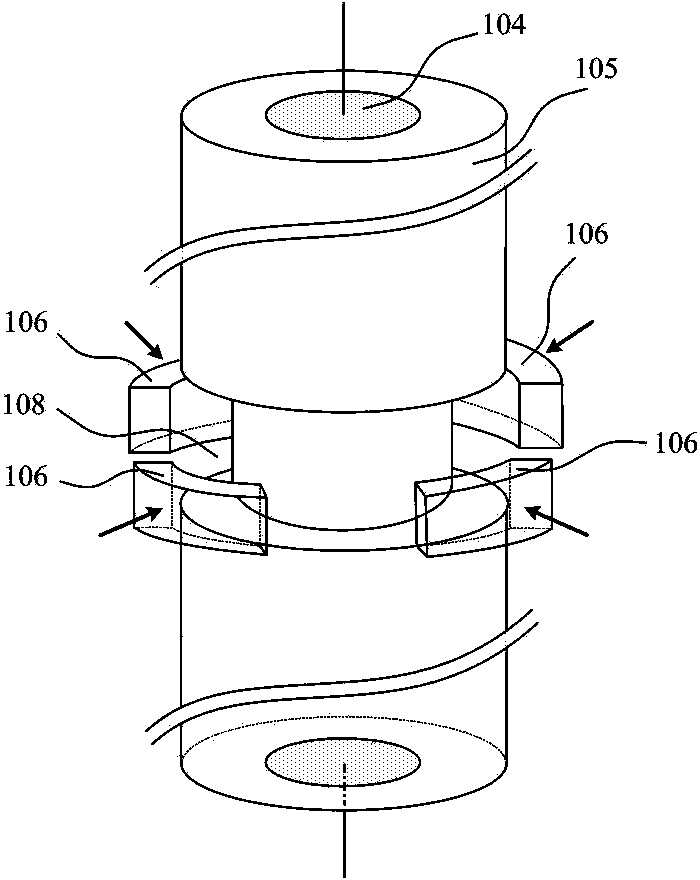
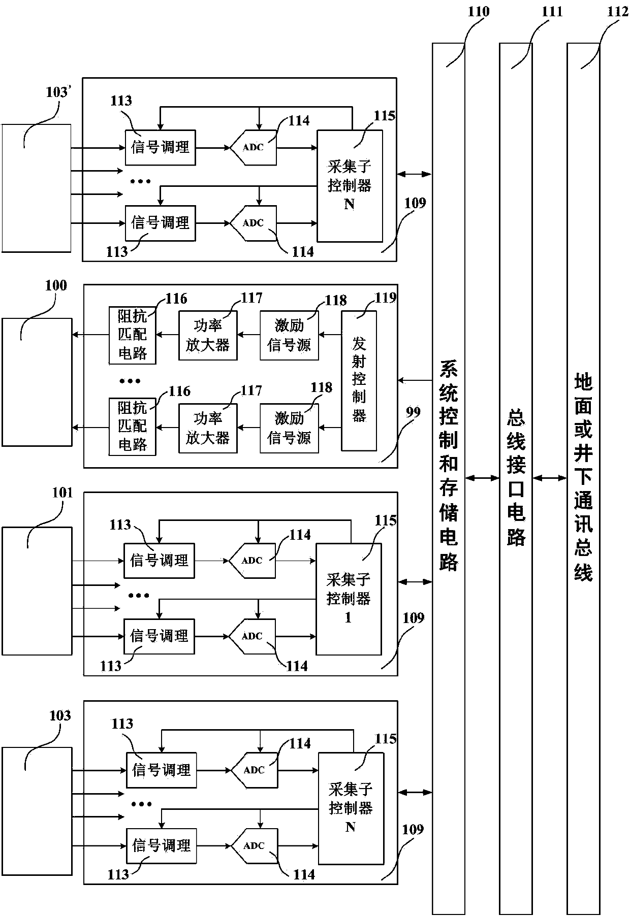
[0034] Such as figure 1 As shown, the LWD device for determining the geological interface beside the well includes a drill collar 105, an acoustic wave transmitting transducer 100 (T), and a near-source acoustic wave receiving transducer 101 (R 0 ), the first sound insulator 102, the second sound insulator 102', the first far source distance acoustic wave receiving transducer array 103 (R 1 ~R n ), the second far-source acoustic wave receiving transducer array 103' (R 1 '~R n ') and control system ( figure 1 not shown in ); the acoustic wave transmitting transducer 100 (T) simultaneously has a monopole radiation function, an orthogonal dipole radiation function and a quadrupole radiation function, and its radiated acoustic signal propagates along the wellbore formation and out of the well; Near-source...


PUM


Abstract

The invention relates to an acoustic logging-while-drilling device and an acoustic logging-while-drilling method. The device comprises a drill collar, an acoustic wave transmitting transducer, a near-spacing acoustic wave receiving transducer, a sound insulator, far-spacing acoustic wave receiving transducer arrays and a control system, wherein acoustic wave signals radiated by the acoustic wave transmitting transducer are propagated in a well wall stratum at which the drill collar is positioned and outside a well; The near-spacing acoustic wave receiving transducer is used for receiving reflected wave signals reflected into the well by a stratum interface beside the well; and the first and second far-spacing acoustic wave receiving transducer arrays are used for receiving acoustic wave signals reflected into the well by the stratum interface beside the well and slide wave signals propagated along the well wall stratum; and the control system controls the acoustic wave transmitting transducer to transmit the acoustic wave signals and performs data processing on the acoustic wave signals of the near-spacing acoustic wave receiving transducer and the far-spacing acoustic wave receiving transducer arrays so as to obtain the lateral distance and azimuth from a well shaft to the stratum interface beside the well. The acoustic logging-while-drilling device is easy for realization of a control circuit, can be used for evaluating the distance and azimuth from a geologic structure body beside the well to the well shaft and is high in engineering application value.

Description

technical field [0001] The invention belongs to the field of applied geophysical well logging, and in particular relates to an acoustic logging while drilling device and method, which are used for determining the distance and orientation of the geological interface beside the well. Background technique [0002] With the increasing demand for exploration and development of oil, natural gas, and mineral deposits and the development of logging technology, more and more highly deviated wells and horizontal wells appear. During the real-time drilling of these wells, in order to improve the accuracy of drilling construction and drilling efficiency, to ensure that the wellbore passes through the production layer and avoid unnecessary losses, it is necessary to effectively track the relative spatial position of the upper and lower boundaries of the formation, and detect the formation boundary information near the drill bit during the drilling process to determine the next step and po...

Claims


Application Information

Patent Timeline
Patent Type & Authority Patents(China)
IPC IPC(8): E21B47/14E21B49/00
Inventor 魏周拓唐晓明陈雪莲谭宝海
Owner CHINA UNIV OF PETROLEUM (EAST CHINA)
Why Eureka
Try Eureka