While-drilling reflecting sound wave measuring sound system

An acoustic measurement, while drilling technology, applied in measurement, earth-moving drilling, wellbore/well components, etc., can solve the problems of inability to obtain the drilling trajectory of the wellbore, low resolution, and difficulty in specific locations, and achieve easy data processing. Interpretation, reduction of interfering signals, the effect of simple device structure

Inactive Publication Date: 2014-04-16
CHINA UNIV OF PETROLEUM (EAST CHINA)
View PDF11 Cites 10 Cited by
  • Summary
  • Abstract
  • Description
  • Claims
  • Application Information

AI Technical Summary

Problems solved by technology

[0003] Existing logging-while-drilling devices usually install many sensors near the drill bit to measure drilling, wellbore and formation-related parameters. For example, resistivity is used to determine the presence of oil and gas, and is used to perform geological However, the detection depth of resistivity is usually only about two or three meters, and it cannot provide information on the orientation of the formation interface relative to the system while drilling
[0004] For the azimuth electromagnetic wave specially used for geosteering, due to its high frequency, although the relative azimuth problem of the formation interface is solved, the detection depth is still limited, and it is difficult to detect reflectors outside the well tens of meters away
However, the logging-while-drilling device based on low-frequency electromagnetic wave detection of geological anomalies around the well often only senses the existence of the anomaly and is difficult to determine its specific location due to its low resolution.
[0005] All in all, for the current measurement-while-drilling system, it is difficult to determine the spatial position of the side-hole reflector, and it is impossible to obtain an optimal wellbore drilling trajectory. Therefore, it is necessary to have a relatively accurate and convenient engineering implementation for detecting well Acoustic system of acoustic wave measurement while drilling for side reflectors

Method used


Image

  • While-drilling reflecting sound wave measuring sound system

Examples


Embodiment Construction

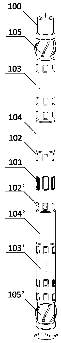
[0025] Such as figure 1 As shown, the sound system for measuring reflected acoustic waves while drilling includes: a drill collar 100, an acoustic wave emitting transducer 101 is arranged outside the middle of the drill collar 100, and the acoustic wave emitting transducer 101 is a single acoustic wave transducer;

[0026] The first close-source acoustic wave receiving transducer 102 and the second close-source acoustic wave receiving transducer 102' are arranged symmetrically with respect to the acoustic wave transmitting transducer 101 in the axial direction of the drill collar 100, and the first close-source acoustic wave receiving transducer Both the device 102 and the second close-source acoustic wave receiving transducer 102' are single acoustic wave transducers;

[0027] The first far-source distance acoustic wave receiving transducer array 103 and the second far-source distance acoustic wave receiving transducer array 103' are arranged symmetrically with respec...


PUM


Abstract

The invention relates to a while-drilling reflecting sound wave measuring sound system which comprises a drill collar. A sound wave transmitting transducer is arranged on the outer side of the middle portion of the drill collar. A first near source distance sound wave receiving transducer and a second near source distance sound wave receiving transducer are symmetrically arranged in the axial direction of the drill collar around the sound wave transmitting transducer. A first far source distance sound wave receiving transducer array and a second far source distance sound wave receiving transducer array are symmetrically arranged in the axial direction of the drill collar around the sound wave transmitting transducer. The first near source distance sound wave receiving transducer and the second near source distance sound wave receiving transducer are placed between the first far source distance sound wave receiving transducer array and a second far source distance sound wave receiving transducer array. The sound wave transmitting transducer and the sound wave receiving transducers are composed of a plurality of arc piezoelectric ceramic crystals in the periphery direction, the structure is simple, circuit control can be easily achieved, and sound insulation between the sound wave receiving transducers and the drill collar is achieved.

Description

technical field [0001] The invention belongs to the field of acoustic well logging, and in particular relates to a sound system for measuring reflected acoustic waves while drilling, which is used for determining the spatial position and relative orientation of reflectors beside wells. Background technique [0002] In recent years, the sonic logging while drilling technology has developed rapidly. Compared with wireline logging, sonic logging while drilling not only has the advantages of real-time measurement of formation compressional The seismic wave velocity model obtained is combined with the seismic exploration data to track the relative spatial position of the upper and lower boundaries of the formation in real time to ensure that the wellbore passes through the production layer and avoid unnecessary losses. [0003] Existing logging-while-drilling devices usually install many sensors near the drill bit to measure drilling, wellbore and formation-related parameters. Fo...

Claims


Application Information

Patent Timeline
Patent Type & Authority Applications(China)
IPC IPC(8): E21B47/14
Inventor 魏周拓陈雪莲
Owner CHINA UNIV OF PETROLEUM (EAST CHINA)
Why Eureka
Try Eureka