Vehicle-mounted self-balancing camera pan-tilt

A self-balancing, pan-tilt technology, applied in vehicle parts, machine/brackets, cameras, etc., can solve the problems such as the inability to fully display the impact and dynamic sense, the rigid picture, the rigid and inanimate picture, etc., to achieve convenient installation and disassembly, Overcoming bumps and swaying, technologically advanced effects

Active Publication Date: 2015-04-22
嘉兴市燕知网络科技有限公司
View PDF6 Cites 1 Cited by
  • Summary
  • Abstract
  • Description
  • Claims
  • Application Information

AI Technical Summary

Problems solved by technology

[0003] In the past, the shooting of moving objects could only be done at a static position or a fixed position relative to the camera. The picture was rigid and had great limitations. It could not fully show the impact and dynamic sense in motion, and the picture was rigid and not vivid.

Method used


Image

  • Vehicle-mounted self-balancing camera pan-tilt
  • Vehicle-mounted self-balancing camera pan-tilt
  • Vehicle-mounted self-balancing camera pan-tilt

Examples


Embodiment Construction

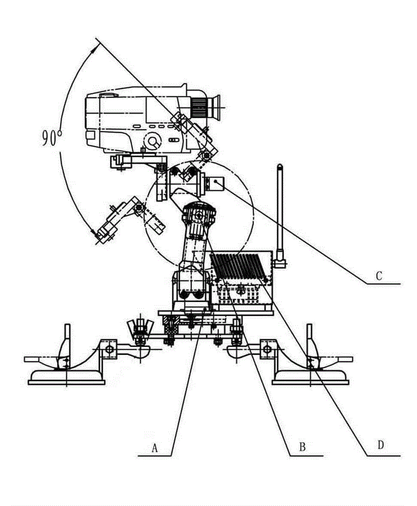
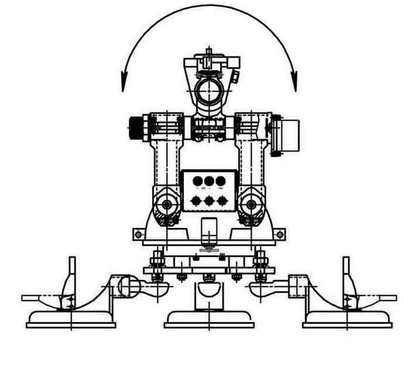
[0025] The vehicle-mounted self-balancing camera platform, as shown in Figure 1, 6~7, includes a horizontal servo motor assembly, a roll servo motor assembly, a pitch servo motor assembly, a servo control device, and a camera device. The servo control device controls the level The horizontal, rolling and pitching direction movements of the servo motor assembly, the rolling servo motor assembly and the pitching servo motor assembly realize the horizontal, rolling and pitching direction movements of the camera device.

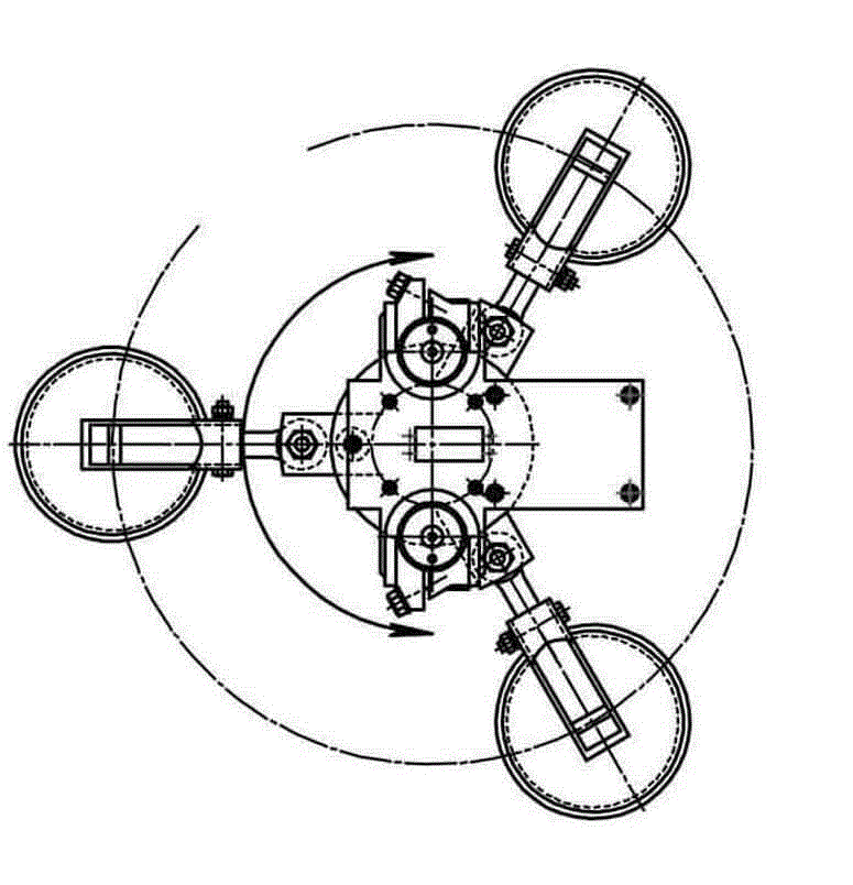
[0026] Such as figure 2 As shown, there is a suction cup fixing part under the horizontal servo motor assembly. The suction cup fixing part includes three vacuum suction cups 01, suction cup connector 02, pan-tilt base 03, pan-tilt damping plate 04 and shock-absorbing element 05, and the suction cup 01 The suction cup connector 02 is connected to the pan-tilt base 03. The suction cup connector 02 is a joint bearing. This connection allows the vacuum suction cup ...


PUM


Abstract

The invention discloses a vehicle-mounted self-balancing camera pan-tilt which comprises a horizontal servo motor assembly, a transverse rolling servo motor assembly, a pitching servo motor assembly, a servo control device and a camera, wherein the servo control device controls horizontal movement, transverse rolling movement, and pitching movement of the horizontal servo motor assembly, the transverse rolling servo motor assembly and the pitching servo motor assembly, so that the horizontal movement, the transverse rolling movement, and the pitching movement of the camera are achieved. The pan-tilt overcomes the defect that a camera picture rocks due to jolt and swinging when a vehicle runs, and ensures that the camera is in a stable and balanced state all the time.

Description

technical field [0001] The invention relates to a vehicle-mounted self-balancing camera platform. Background technique [0002] For a long time, when shooting movies and TV on moving vehicles, undulating and swaying ships and aerial camera planes, the severe bumps make the captured pictures inevitably shake and blur, and the captured video images make it easy for viewers to Visual fatigue occurs, resulting in the inability to watch normally. For a long time, this has been a difficult problem that has puzzled the majority of film and TV camera workers. [0003] In the past, the shooting of moving objects could only be done at a static position or with a fixed camera position at a relative position. The picture is rigid and has great limitations. It cannot fully show the impact and dynamic sense in motion, and the picture is rigid and not vivid. It is even more powerless for some sports scenes with special requirements, such as fierce off-road vehicle competitions, sports an...

Claims


Application Information

Patent Timeline
Patent Type & Authority Patents(China)
IPC IPC(8): F16M11/42F16M11/04F16M11/18G03B17/56F16F15/02B60R11/04
Inventor 崔新巍
Owner 嘉兴市燕知网络科技有限公司
Why Eureka
Try Eureka