
Air conditioner

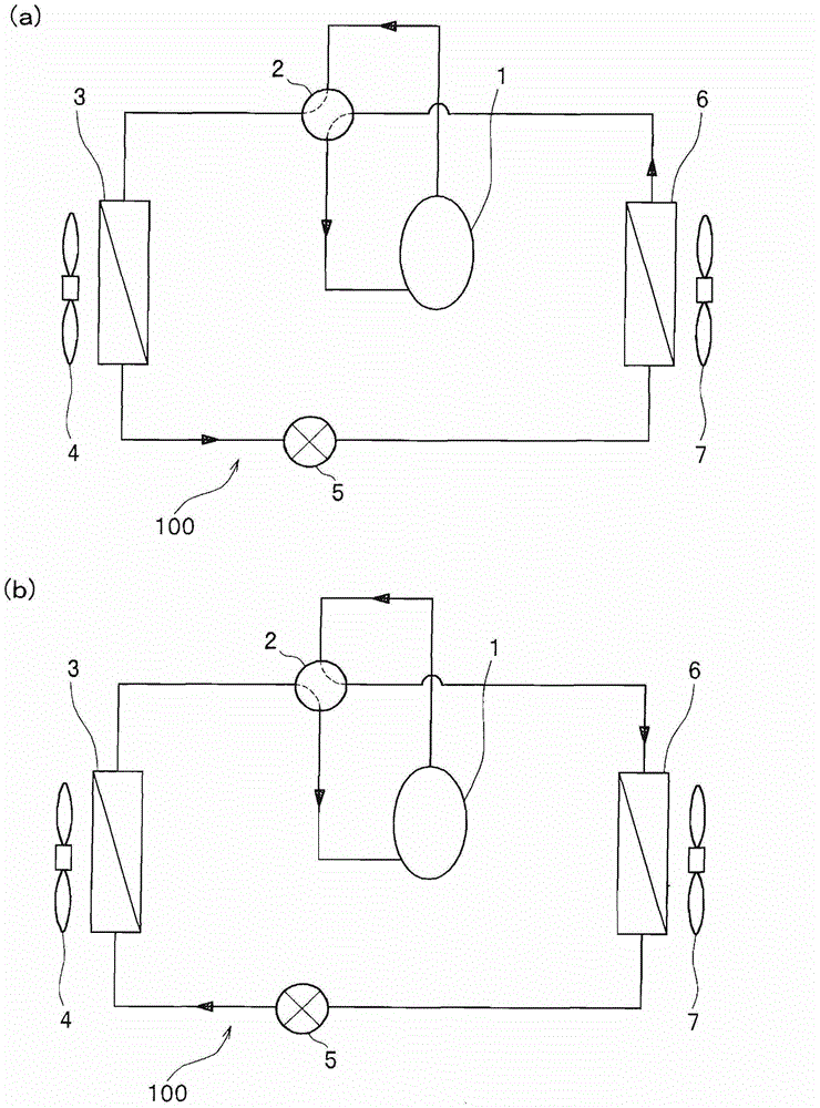
An air conditioner and heat transfer tube technology, which is applied in the field of air conditioners, can solve the problems of insufficient technology for preventing heat conduction and improving thermal performance, and achieve the effect of improving heat transfer performance

Active Publication Date: 2013-06-12
HITACHI JOHNSON CONTROLS AIR CONDITIONING INC
View PDF6 Cites 1 Cited by
  • Summary
  • Abstract
  • Description
  • Claims
  • Application Information

AI Technical Summary

Problems solved by technology

However, using only such a technology is not sufficient as a technology for preventing heat conduction and improving thermal performance.

Method used


Image

  • Air conditioner
  • Air conditioner
  • Air conditioner

Examples


no. 2 Embodiment approach

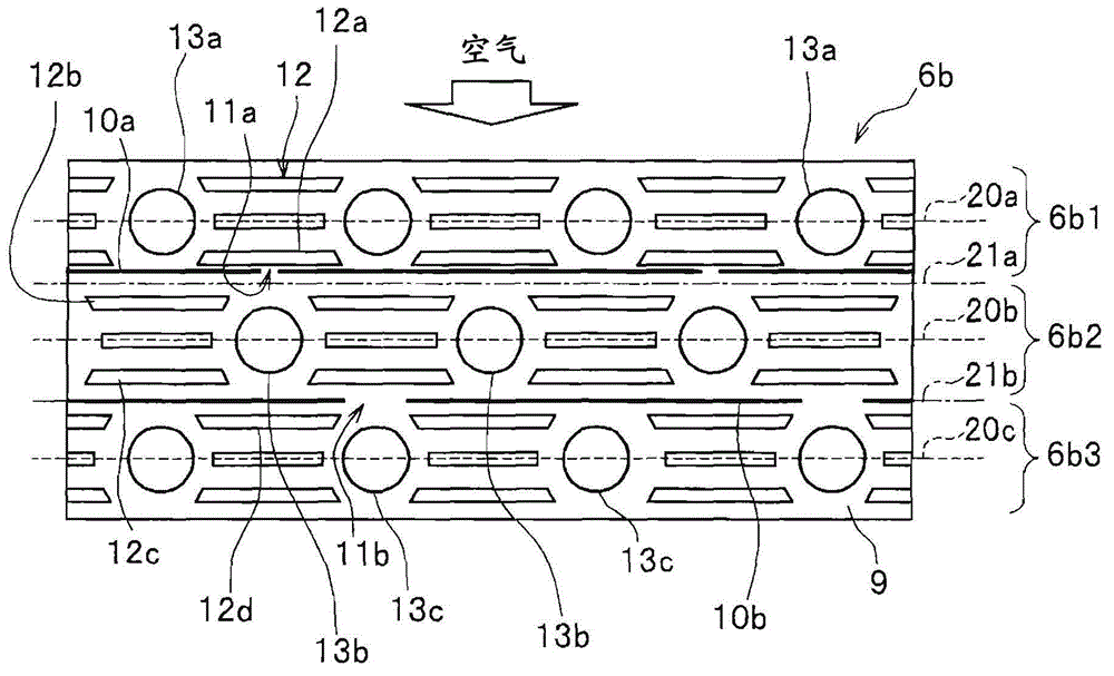
[0073] Next, refer to Figure 9 as well as Figure 10 , and the structure of the reheater 6bB of the second embodiment will be described. In addition, in the following description, the point of difference with the above-mentioned reheater 6b is mainly demonstrated, and the description of the same content is abbreviate|omitted for simplification. And, with image 3 The same components of the shown reheater 6b are assigned the same symbols, and detailed description thereof will be omitted. In addition, the configurations of the air conditioners other than the reheater 6b are the same as those described above.

[0074] Figure 9 as well as Figure 10 In the shown reheater 6bB, the positions of the connecting parts 11a, 11b are different from those in the above-mentioned reheater 6b. Specifically, the connector 11 a in the reheater 6 bB is provided at the center (substantially at the center) of the stage pitch of the heat transfer tubes 13 b in the second row. That is, it i...

no. 3 Embodiment approach

[0082] Next, refer to Figure 11 , and the structure of the reheater 6bC of the third embodiment will be described. It should be noted that in the following description, the main description is related to image 3 For the differences between the above-mentioned reheaters 6b, the description of the same content will be omitted for simplification. And, with image 3 The same components of the shown reheater 6b are assigned the same symbols, and detailed description thereof will be omitted. In addition, the configurations of the air conditioners other than the reheater 6bC are the same as those described above. In addition, in Figure 11 In , the description of the centerlines 20a, 20b, and 20c and the centerlines 21a and 21b between rows is omitted.

[0083] In the reheater 6bC, the thickness ratio of the heat transfer tube 13a image 3 The thickness of the heat transfer tube 13a in the shown reheater 6b is thick. That is, the inner diameter of the heat transfer tube 13a ...


PUM


Abstract

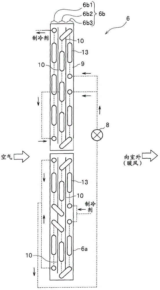
The invention provides an air conditioner which is further improved in terms of performance of heat transfer between the air conditioner and the air. In a heat exchanger (6), a plurality of first heat transfer pipes arranged on a windward side of a fin and a plurality of second heat transfer pipes arranged on a leeward side of the fin are disposed along substantially the same direction. Cutting portions are disposed among the plurality of first heat transfer pipes, and cutting grooves are disposed between the plurality of first heat transfer pipes and the plurality of second heat transfer pipes. A connecting portion is disposed between one cutting groove and the adjacent cutting groove and is shorter than a distance between each two heat transfer pipes among the plurality of first heat transfer pipes, and the cutting portions longer than the connecting portions are disposed adjacent to the connecting portions. The cutting grooves arranged between the plurality of first heat transfer pipes and the plurality of second heat transfer pipes are configured to be eccentric to the plurality of first heat transfer pipes or the plurality of second heat transfer pipes relative to a central line of a first column.

Description

technical field [0001] The present invention relates to air conditioners. Background technique [0002] In an air conditioner (air conditioner, air conditioner), when a heat exchanger is used as a condenser, the temperature difference between the refrigerant temperature in the condensation area and the refrigerant temperature in the subcooling area becomes large. Therefore, when a cross-fin tube (cross-fin tube) type heat exchanger is formed in a plurality of rows, the heat retained by the refrigerant in the condensation area is conducted between the rows of fins (conduction across rows), and is transferred to the subcooling area. The phenomenon that the low-temperature refrigerant in the domain moves. Therefore, there is a problem that performance as a condenser decreases. As a technique for solving this problem, the technique described in Patent Document 1 is known. [0003] prior art literature [0004] patent documents [0005] Patent Document 1: Japanese Patent Lai...

Claims


Application Information

Patent Timeline
IPC IPC(8): F25B39/04
Inventor 关谷祯夫米田广台坂恒山崎洋
Owner HITACHI JOHNSON CONTROLS AIR CONDITIONING INC
Learn More