
Fiber grating vertical strain sensor

A technology of strain sensor and optical fiber grating, which is applied in the direction of instruments, optical devices, measuring devices, etc., can solve the problems of test data deviation, large size, difficult combination of test piece block and structural layer, etc., to achieve measurement and avoid strain distribution the effect of the change

Active Publication Date: 2013-06-12
SHANDONG UNIV
View PDF5 Cites 1 Cited by
  • Summary
  • Abstract
  • Description
  • Claims
  • Application Information

AI Technical Summary

Problems solved by technology

Practice shows that the above method has some disadvantages: it is difficult to combine the test piece block and the structural layer well, the moisture-proof effect is poor, and the solder joints of the strain gauge are easy to fall off
The sensor itself has a high modulus and a large size. As a foreign body, the original stress field of the medium is changed, and the strain field must also be changed, resulting in the deviation of the test data.

Method used


Image

  • Fiber grating vertical strain sensor
  • Fiber grating vertical strain sensor

Examples


Embodiment Construction

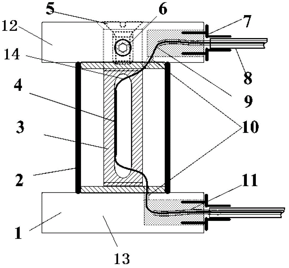
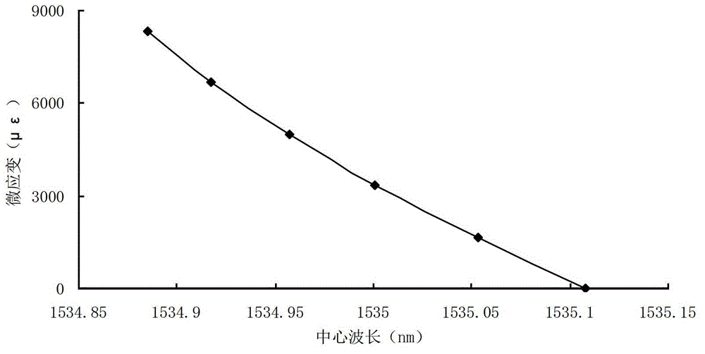
[0027] Attached below figure 1 And attached figure 2 The present invention is described in detail:

[0028] The fiber grating vertical strain sensor of the present invention mainly consists of a sensitive grating 4, a temperature compensation grating 11, a fixed base 1, a protective shell 2, an inner hollow pillar 3, a fixed screw 5, an orientation screw 6, an optical fiber steering hole 10, and an optical fiber lead-out protection Component 7, armored optical cable 8 and pigtail 9 etc. composition.

[0029] Fixed base 1 comprises upper base 12 and lower base 13; Pasted on the inner wall of the hollow pillar 3, the optical fiber 14 penetrates from the side of the upper base 12, passes through the inner hollow pillar 3, and passes out from the side of the lower base 13. The side of the upper base 12 and the side of the lower base 13 are on the same side of the hollow pillar 3 . A protective casing 2 is provided on the outside of the hollow pillar 3 . The upper base 12 is ...


PUM


Abstract

The invention particularly discloses a fiber grating vertical strain sensor, which comprises a fixed base, a hollow supporting column, optical fibers and a sensitive grating, wherein the fixed base comprises an upper base and a lower base, the hollow supporting column is arranged between the upper base and the lower base, the sensitive grating is arranged on the optical fibers and is bonded on the inner wall of the hollow supporting column, the optical fibers enter from the side surface of the upper base, run through the hollow supporting column and go out from the side surface of the lower base, temperature compensation gratings are arranged on the optical fibers which penetrate through the upper base and the lower base, and the two ends of the optical fibers are connected with fiber grating demodulators. The fiber grating vertical strain sensor has the advantages that the similarity between the material of the sensor and the material of an environment is realized through the hollow supporting column, the change of material strain distribution of the base due to embedment of the sensor is effectively avoided, and the measurement of vertical strain of roadbed materials under the effect of external acting force is realized.

Description

technical field [0001] The invention relates to the field of optical fiber sensing, in particular to an optical fiber grating vertical strain sensor for measuring the vertical strain of asphalt pavement. Background technique [0002] Since the 20th century, my country's road traffic construction has developed at an unprecedented speed. More than 95% of my country's high-grade roads are asphalt pavement, the reason is that it has the following good properties: (1) Sufficient mechanical strength, asphalt pavement can well withstand various effects of vehicle loads on the road surface (2) Certain elastic and plastic deformation ability, able to withstand load without damage; (3) Good adhesion with automobile tires, which can ensure driving safety; (4) High shock absorption brought by plastic properties , can make the car run fast, stable and without noise; (5) no dust, easy to clean and wash; (6) easy maintenance, and the asphalt road surface can be recycled. However, we should...

Claims


Application Information

Patent Timeline
Patent Type & Authority Applications(China)
IPC IPC(8): G01B11/16
Inventor 王静王正方隋青美王宁蒋善超杨帅李晓飞贾磊张法业曹玉强
Owner SHANDONG UNIV
Learn More