Electric-vibration model-based power transformer failure diagnosis method

A technology for power transformers and vibration models, which is used in the measurement of electrical variables, instruments, and electrical measurements, can solve the problems of complex vibration signals on the surface of the transformer tank wall, different vibrations, and difficulty in improving the accuracy and applicability of the model, and achieves elimination. Reflect the possibility of insensitive or incomplete, improve the accuracy, the effect of good practicability

Active Publication Date: 2013-06-12
STATE GRID ZHEJIANG WENLING POWER SUPPLY +2
View PDF5 Cites 23 Cited by
  • Summary
  • Abstract
  • Description
  • Claims
  • Application Information

AI Technical Summary

Problems solved by technology

Furthermore, the vibration on the wall of the transformer oil tank is affected by factors such as the mechanical structure of the transformer, the transmission path of vibration, and the response of the oil tank wall itself to vibration, which makes the vibration signals on the surface of the transformer oil tank wall quite complicated, and the vibrations at different positions are different. same
A large number of studies have shown that it is difficult to obtain the vibration characteristics and fault information inside the transformer by simply monitoring and analyzing the vibration signal of a single measuring point on the surface of the oil tank. However, Garcia B.'s model is only modeled independently for one vibration measuring point. It is also one of the main reasons why the accuracy and applicability of the model are difficult to improve

Method used


Image

  • Electric-vibration model-based power transformer failure diagnosis method
  • Electric-vibration model-based power transformer failure diagnosis method
  • Electric-vibration model-based power transformer failure diagnosis method

Examples


Embodiment Construction

[0042] In order to describe the present invention more specifically, the technical solutions of the present invention will be described in detail below in conjunction with the accompanying drawings and specific embodiments.

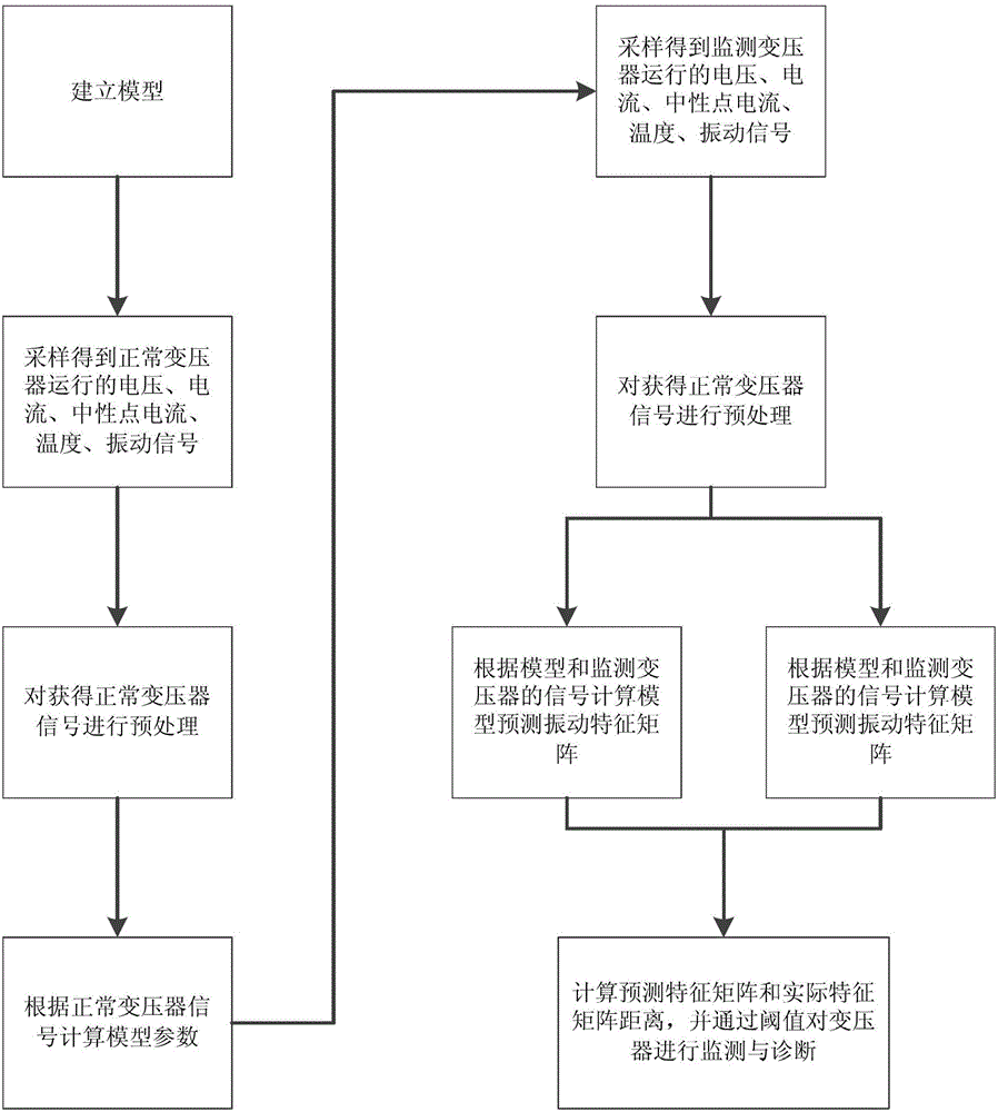
[0043] Such as figure 1 As shown, a power transformer fault diagnosis method based on the electric-vibration model includes the following steps:

[0044] First, build the electro-vibration model:

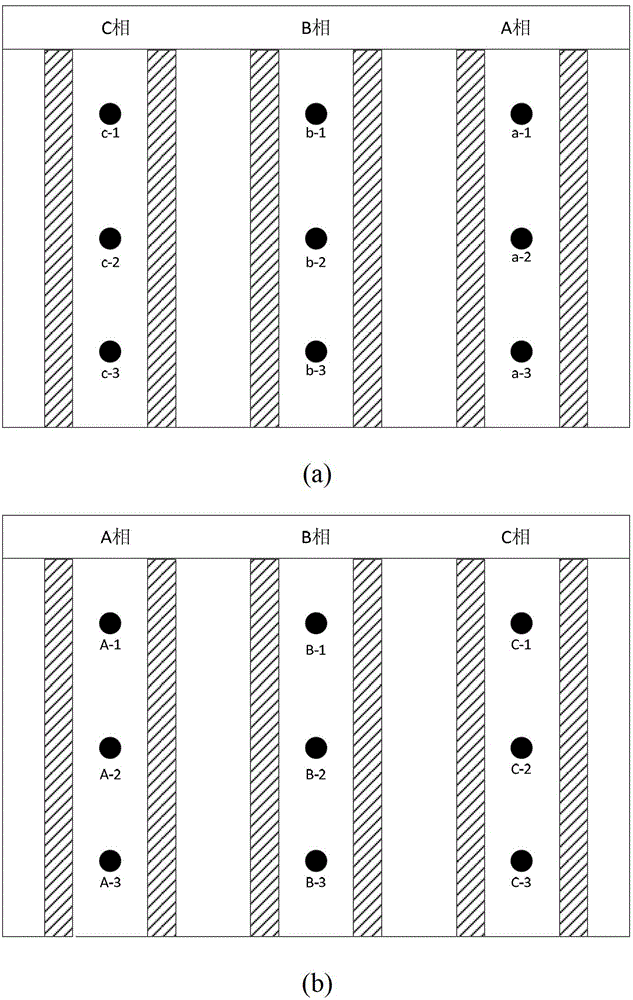
[0045] (1) Collect the output voltage signal, load current signal and oil temperature signal of the power transformer under normal operating conditions; at the same time, arrange multiple vibration measuring points on the outer surface of the transformer oil tank, and collect the corresponding vibration signals of each measuring point;

[0046] Such as figure 2 As shown, a total of 18 ICP acceleration sensors are installed on the surface of the transformer oil tank (9 on the low-voltage side and 9 on the high-voltage side) when the transformer is in normal o...


PUM


Abstract

The invention discloses an electric-vibration model-based power transformer failure diagnosis method, which comprises the following steps of: training to establish an electric-vibration model by acquiring a voltage signal, a current signal, an oil temperature signal and a plurality of vibration measuring points of a transformer; and performing failure diagnosis on the transformer by comparing measured data of vibration with predicted data obtained through the model. According to the method, both input and output of the vibration model are related with actual vibration, and signal, transformer parameters and the like can be measured or acquired; the method has extremely high practicability; a fundamental frequency component of the vibration of the transformer is considered by the model, and high order harmonic is also included, and some failures which cannot be reflected by the fundamental frequency vibration can be discovered; and the vibration of a plurality of measuring points of the oil tank wall of the transformer is considered by the model, the possibility that the internal vibration of the transformer is not inflexibility or incompletely reflected by single-point vibration is eliminated, and the accuracy for performing monitoring diagnosis of the transformer by using the electric-vibration model is improved.

Description

technical field [0001] The invention belongs to the technical field of electric equipment fault detection, and in particular relates to a power transformer fault diagnosis method based on an electric-vibration model. Background technique [0002] When the power transformer is running stably, the vibration of the iron core mainly comes from the magnetostriction of the ferromagnetic material, while the vibration of the winding is generated by the electromagnetic force of the energized winding in the leakage magnetic field. The vibration of the winding and iron core is transmitted to the surface of the transformer oil tank through the internal connection of the transformer and the transmission of insulating oil, and vibration is generated on the surface of the oil tank. Therefore, the status and fault information of the transformer winding and iron core can be monitored through the vibration measurement and analysis of the surface of the transformer oil tank. The online monito...

Claims


Application Information

Patent Timeline
Patent Type & Authority Applications(China)
IPC IPC(8): G01R31/00
Inventor 黄海陈祥献林土方郭才福王泽波林爱弟郭洁郑婧潘成峰夏冰松李汶
Owner STATE GRID ZHEJIANG WENLING POWER SUPPLY
Why Eureka
Try Eureka