
Automatic sound emission monitoring method and automatic sound emission monitoring device

A technology of automatic monitoring and monitoring devices, which is applied in the fields of earthwork drilling, program control, instruments, etc., and can solve problems such as inability to realize automatic monitoring, sensor sticking, troublesome operation, etc.

Inactive Publication Date: 2013-06-12
CHINA UNIV OF MINING & TECH
View PDF8 Cites 9 Cited by
  • Summary
  • Abstract
  • Description
  • Claims
  • Application Information

AI Technical Summary

Problems solved by technology

However, in order to detect the high-frequency acoustic emission signals produced by the cracking of coal and rock formations, the acoustic emission sensor must be close to coal and rock, which brings difficulties to practical applications
There are two commonly used methods at present, one is to install the acoustic emission sensor in the hollow steel pipe, and insert the hollow steel pipe into the coal rock and rock through drilling; These two methods are not ideal, the former is not only cumbersome to operate, but also the acoustic emission sensor inserted into the borehole cannot guarantee to be close to the coal or rock; Glue the sensor, even if it is glued, it will affect the sensitivity of the sensor due to the isolation of the glue
Furthermore, neither of the above two monitoring methods can realize automatic monitoring.

Method used


Image

  • Automatic sound emission monitoring method and automatic sound emission monitoring device
  • Automatic sound emission monitoring method and automatic sound emission monitoring device
  • Automatic sound emission monitoring method and automatic sound emission monitoring device

Examples


Embodiment Construction

[0013] An embodiment of the present invention will be further described below in conjunction with accompanying drawing:

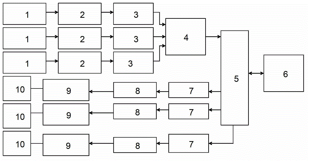
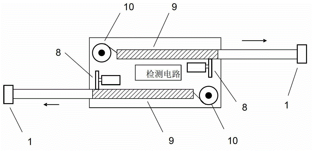
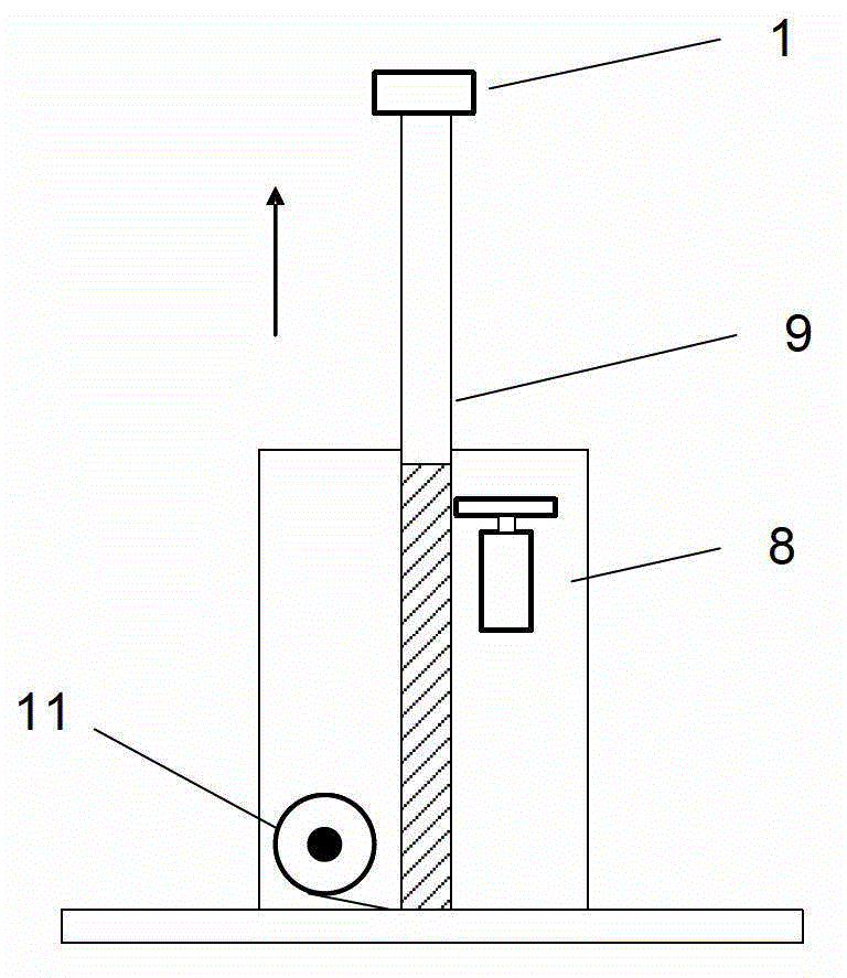
[0014] Such as figure 1 As shown, the acoustic emission automatic monitoring method and device of the present invention include a single-chip microcomputer 5, and the input terminals of the single-chip microcomputer 5 are respectively connected with an A / D converter 4 and a communication circuit 6, and the communication circuit includes a wireless communication and a wired communication circuit , the wireless communication is used to transmit the acoustic emission monitoring signal to the ground receiving base station, the wired communication is used for the communication between the monitoring device and the mobile carrier control circuit, and the input ends of the A / D converter 4 are respectively connected with a plurality of acoustic emission detection circuits, The output end of the single-chip microcomputer 5 is connected with a plurality of telescopic...


PUM


Abstract

The invention relates to an automatic sound emission monitoring method and an automatic sound emission monitoring device, which is suitable for monitoring a mine or tunnel rock layer cracking signal. The device consists of a sound emission sensor, a front-mounted amplifier, a band-pass filter, an analog-digital (AD) converter, a single chip microprocessor, a communication circuit, a vertical rotary retractable rod, a transverse rotary retractable rod, a drive motor, a motor control circuit and a winding turntable. The drive motor is controlled through the motor control circuit, so that the vertical rotary retractable rod and the transverse rotary retractable rod stretch, the sound emission sensor which is installed on the end of the retractable rod is close to a rock wall to be monitored, a lead of the sound emission sensor is wound on the winding turntable through a retractable rod in a hollow way, the tail end is inputted to the input end of the front-mounted amplifier, the output of the front-mounted amplifier is connected to the input end of the band-pass filter, the output of the band-pass filter is connected to the input end of the AD converter, the output of the AD converter is connected to the input end of the single chip microprocessor, the output of the single chip microprocessor is connected to the input end of the communication circuit, a sound emission collection signal is transmitted to a monitoring base station in a wireless way, and automatic monitoring of a sound emission signal is realized.

Description

technical field [0001] The invention relates to an automatic monitoring method and device, in particular to an acoustic emission automatic monitoring method and device for monitoring rock formation rupture signals in mines or tunnels. Background technique [0002] At present, acoustic emission reception has begun to be used in the monitoring of mine coal rock and tunnel rock formation rupture, so as to realize the monitoring and early warning of rock burst and water inrush disasters. However, the acoustic emission sensor must be close to the coal rock and rock to detect the high-frequency acoustic emission signal generated by the cracking of coal rock and rock formation, which brings difficulties to practical application. There are two commonly used methods at present, one is to install the acoustic emission sensor in the hollow steel pipe, and insert the hollow steel pipe into the coal rock and rock through drilling; These two methods are not ideal, the former is not only ...

Claims


Application Information

Patent Timeline
IPC IPC(8): G05B19/042E21D9/00
Inventor 童敏明童紫原
Owner CHINA UNIV OF MINING & TECH
Learn More