Piezoelectric driven linear motion device
A linear motion, piezoelectric drive technology, applied in the direction of generator/motor, piezoelectric effect/electrostrictive or magnetostrictive motor, electrical components, etc., can solve the problems of small driving force and complex structure
- Summary
- Abstract
- Description
- Claims
- Application Information
AI Technical Summary
Problems solved by technology
Method used
Image

Examples
specific Embodiment approach 1
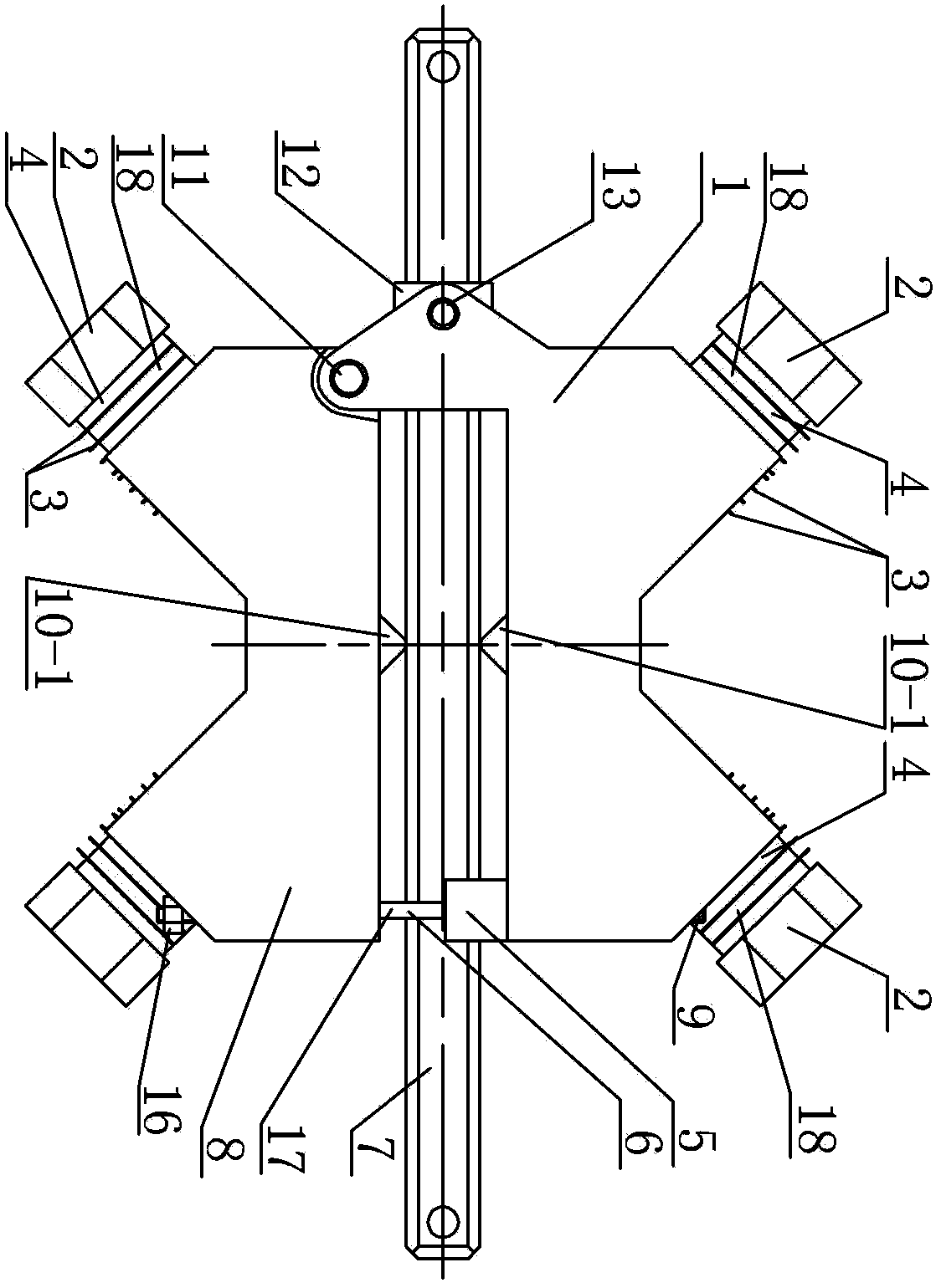
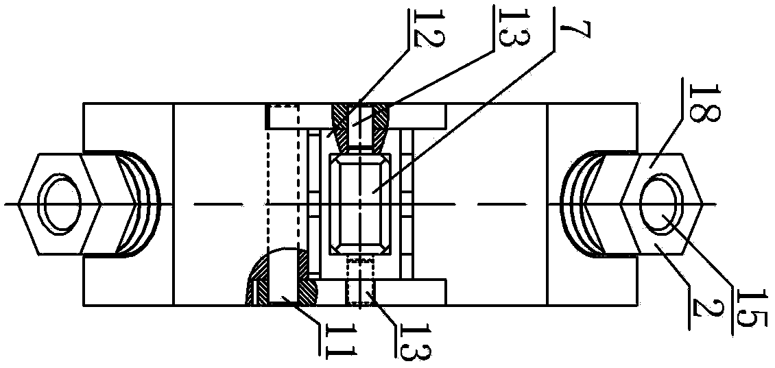
[0010] Specific implementation mode one: combine Figure 1 to Figure 5 Describe this embodiment, a piezoelectric drive linear motion device of this embodiment includes an upper support frame 1, a lower support frame 8, a linear guide rail 7, a guide sleeve 12, two sets of pretensioning mechanisms 17 and two sets of stators, each set of stators Including two vibrators 18, each vibrator 18 includes a front end cover 10, a rear end cover 2, an electrode sheet 3 and a piezoelectric ceramic 4, and an electrode sheet 3 and a piezoelectric ceramic 4 are arranged between the front end cover 10 and the rear end cover 2 and The four are connected as one, the front end covers 10 of the two vibrators 18 of each set of stators are connected as a whole, and the angle β between the center lines of the two vibrators 18 is 30° to 90°, the joint of the two vibrators 18 In order to drive the foot 10-1, the upper support frame 1 and the lower support frame 8 are respectively arranged on the upper...
specific Embodiment approach 2
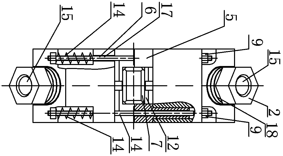
[0012] Specific implementation mode two: combination figure 2 and image 3 Describe this embodiment, each set of pretensioning mechanisms 17 in this embodiment includes a connecting rod 6, a first nut 16 and an elastic member 14, the connecting rod 6 passes through the upper support frame 1 and the lower support frame 8, and is located at the lower support frame 8 An elastic member 14 is pierced through the connecting rod 6 at the lower end, the lower end of the connecting rod 6 is threadedly connected with the first nut 16 , and the upper end of the connecting rod 6 is detachably connected with the upper supporting frame 1 . The elastic member of this embodiment is preferably an elastic member with low rigidity. In this embodiment, the compression amount of the elastic member is adjusted by tightening the first nut, and the driving feet of the upper and lower stators (two vibrators in each stator) are preloaded. To the linear guide rail, and realize the adjustment of the pr...
specific Embodiment approach 3
[0013] Specific implementation mode three: combination figure 2 and image 3 This embodiment will be described. The two elastic members 14 in this embodiment are both coil springs. The present embodiment preferably uses the little helical spring of rigidity, and the nut of this embodiment can be hexagonal nut, adjusts the compression amount of helical spring by tightening the first nut, the driving feet of two stators up and down (two in each stator) The vibrator) is preloaded onto the linear guide rail. Due to the small spring stiffness, the preload can be calculated quantitatively by quantitatively adjusting the compression of the spring, so that the preload can be applied quantitatively. Due to the small amount of wear, the preload caused by wear The amount of change is negligible, and the effect of adjusting the size of the pretightening force is better. Others are the same as in the second embodiment.
PUM
 Abstract
Description
Claims
Application Information
 - R&D
- Intellectual Property
- Life Sciences
- Materials
- Tech Scout
- Unparalleled Data Quality
- Higher Quality Content
- 60% Fewer Hallucinations
Browse by: Latest US Patents, China's latest patents, Technical Efficacy Thesaurus, Application Domain, Technology Topic, Popular Technical Reports.
© 2025 PatSnap. All rights reserved.Legal|Privacy policy|Modern Slavery Act Transparency Statement|Sitemap|About US| Contact US: help@patsnap.com