
Quick flow type dispersing and mixing machine with three-vane push type rotor

A propellant and mixer technology, which is applied to mixers, mixers, chemical/physical/physical-chemical stationary reactors with rotary stirring devices, etc. Function and other problems, to achieve the effect of uniform mixing, fast mixing speed and short response time

Inactive Publication Date: 2013-06-19
SHANGHAI FLUKO TECH DEV
View PDF3 Cites 0 Cited by
  • Summary
  • Abstract
  • Description
  • Claims
  • Application Information

AI Technical Summary

Problems solved by technology

[0003] (1) The motor and the main shaft are rigidly connected, if the load is too large, the motor is easily damaged
[0004] (2) The light powder floats on the liquid surface and is difficult to be brought into the liquid by the stirring paddle, and it is difficult to stir evenly
[0005] (3) No shear function, the mixture is easy to agglomerate

Method used


Image

  • Quick flow type dispersing and mixing machine with three-vane push type rotor
  • Quick flow type dispersing and mixing machine with three-vane push type rotor

Examples


Embodiment Construction

[0014] The present invention will be further described below in conjunction with specific implementation examples and drawings, but the protection scope of the present invention should not be limited by this.

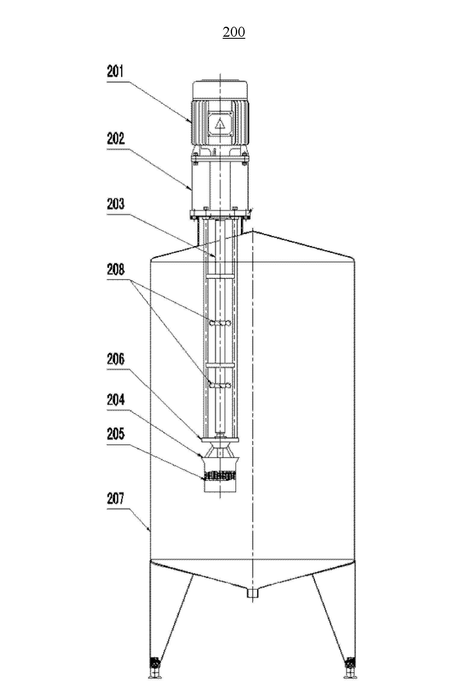
[0015] figure 2 It is a schematic structural diagram of a quick-flow dispersing mixer with a three-blade propeller rotor according to an embodiment of the present invention. As shown in the figure, the jet flow dispersing mixer 200 with a three-blade propeller rotor can include: a motor 201 to provide power, a coupling 202 that connects the motor 201 and a main shaft 203, and a main shaft 203 to transmit power, which has a shearing function. The stator 204, the rotor 205 that pushes the liquid to flow, and the reactor 207 that contains the dispersed mixed medium.

[0016] The jet flow dispersing mixer 200 with a three-blade propeller rotor may further include an inverted impeller 208 that pushes the mixed liquid to rotate counterclockwise, three uprights 206 that make the ...


PUM


Abstract

The invention provides a high-efficiency quick flow type dispersing and mixing machine with a three-vane push type rotor. A stator and a rotor can be dismantled, materials are uniform in particle size after being dispersed and mixed, dispersing time is short, dispersing and mixing efficiency is improved, and production process is optimized. The quick flow type dispersing and mixing machine with the three-vane push type rotor comprises a motor, a coupler, a main shaft, a stator fixed upright, the stator and the rotor, wherein a device flange of the coupler is connected with a flange of a reaction still, the upper end of the stator fixed upright is arranged on the lower portion of the device flange, the stator fixed upright is connected with the stator in a detachable mode, the rotor is connected with the main shaft in a detachable mode, the stator is a guide cylinder, and a round hole or a chute which plays a role in cutting is formed on a cylinder body of the guide cylinder. The rotor is a three-vane push type rotor, the rotor is inside a cavity of the stator, the motor is connected with the coupler, the coupler enables the main shaft and the motor to be connected with each other, and therefore the motor can drive the main shaft to rotate.

Description

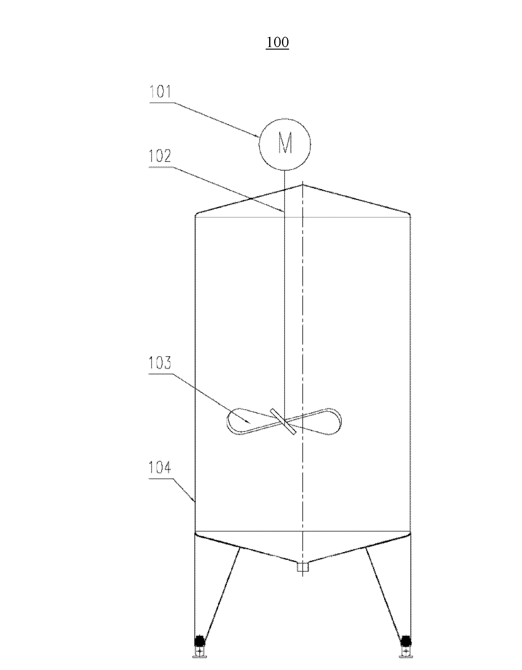
Technical field [0001] The invention relates to a mixer, in particular to a dispersion mixer. Background technique [0002] figure 1 It is a schematic structural diagram of a dispersing mixer 100. The dispersing mixing equipment 100 is mainly composed of a motor 101, a main shaft 102, and a blade 103. There are different types of liquids or mixtures of liquids and light powders in the reactor 104 in advance, and then the motor 101 drives the spindle 102 to drive the paddle 103 to rotate, and finally the different types of liquids or liquid and powder mixtures are dispersed in the reactor 104 mixing. The disadvantages of the aforementioned dispersing mixer 100 include: [0003] (1) The motor and the main shaft are rigidly connected. If the load is too large, the motor is easily damaged. [0004] (2) Light powder floating on the liquid surface is difficult to be carried into the liquid by the stirring blade, and it is difficult to stir uniformly. [0005] (3) Without shearing functio...

Claims


Application Information

Patent Timeline
IPC IPC(8): B01F7/18B01J19/18
Inventor 周宏斌
Owner SHANGHAI FLUKO TECH DEV
Learn More