Novel desulfuration slag rake
A new type of slag scraping technology, applied in charge control, lighting and heating equipment, furnace components, etc., can solve the problems of long wedge pin slag scraping rake, small connection area of slag scraper, deformation and scrapping of slag scraper, etc. To achieve the effect of convenient operation, reduce slag removal time and reduce manufacturing cost
Inactive Publication Date: 2013-06-19
TIANJIN TIANTIE METALLURGICAL GRP
View PDF0 Cites 2 Cited by
- Summary
- Abstract
- Description
- Claims
- Application Information
AI Technical Summary
Problems solved by technology
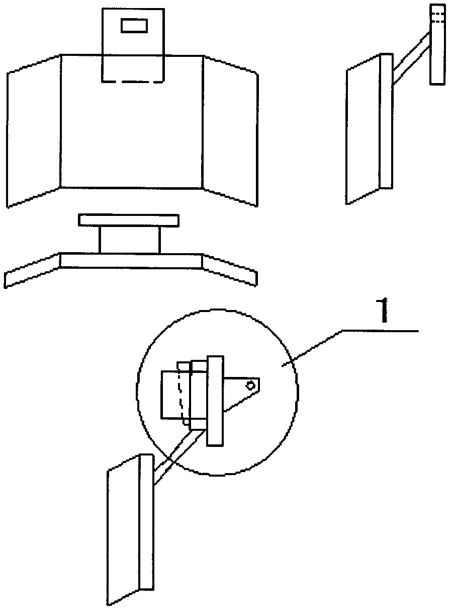
[0003] The connection between the slag rake and the slag scraper is connected by wedge pins. The connection area with the slag scraper is small, and it is easy to deform and scrap the slag scraper. When the deformed slag scraper is difficult to disassemble, the wedge pin is sometimes difficult to pull out. It takes a long time to replace the slag rake
Method used
View moreImage
Smart ImageViewing Examples

Examples
Embodiment Construction
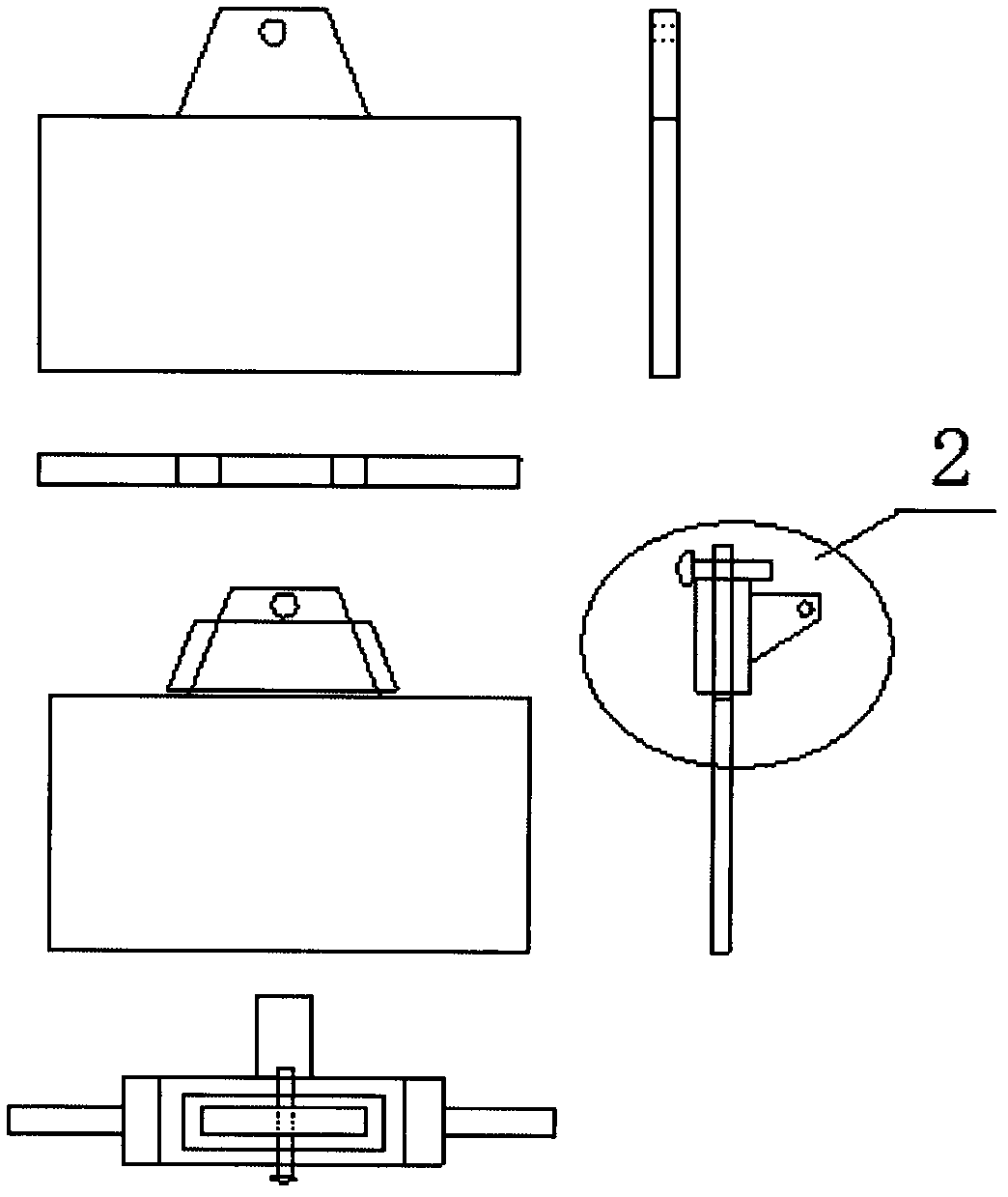
[0015] 1. Use gas cutting to remove the original protruding rectangular body that can be hung with a slag rake.
[0016] 2. Weld a trapezoidal hole at the connection part that can be directly put into the slag rake, and the width is consistent with the thickness of the slag rake.
Login to View More PUM
 Abstract
The invention provides an integrated desulfuration slag rake, wherein manufacturing of an original slag rake is simplified, and the novel desulfuration slag rake does not have a welding portion. Strength of the novel desulfuration slag rake is enhanced, service life of the novel desulfuration slag rake is prolonged, and the novel desulfuration slag rake is flexible and convenient to use. Original wedge pin connection is changed into the connection method of surface-to-surface contact, a protruded rectangular body which can be used for hanging of the slag rake is omitted, a connection trapezoid hole is welded on a connection portion, the slag rake can be placed into the connection trapezoid hole, and the width of the connection trapezoid hole is consistent with the thickness of the slag rake. During installation, a connection port of the slag rake is directly and wholly inserted into the trapezoid hole to form the surface-to-surface contact, and an inserting bolt is placed on the trapezoid hole to prevent falling-off. No stress exists, so that no deformation occurs. Replacement is convenient and rapid, manufacturing cost is lowered, and drossing efficiency is improved.
Description
Technical field: [0001] A new type of slag rake for desulfurization. The slag rake is the main tool for slag removal in the pretreatment of molten iron. It is connected with the slag removal arm of the slag removal machine with iron pins. The action depends on the movement of the slag rake on the surface of the molten iron to remove the desulfurization slag to achieve the purpose of desulfurization. The slag must be removed, otherwise it will cause back sulfur and affect the desulfurization effect. Background technique: [0002] At present, the manufacture of the slag rake is complicated. There are 6 parts welded together, and there are 12 weld seams. Due to the large number of weld seams, due to the influence of molten iron and production rhythm during the slag removal process, it is affected by extreme cold and extreme heat. It is easy to crack or corrode from the welding seam first, resulting in a low service life. In addition, due to the large number of welding seams, it...
Claims
Login to View More Application Information
Patent Timeline
 Patent Type & Authority Applications(China)
IPC IPC(8): B22D43/00F27D3/15
Inventor 史湘东张宏锦
Owner TIANJIN TIANTIE METALLURGICAL GRP
Features
- R&D
- Intellectual Property
- Life Sciences
- Materials
- Tech Scout
- Unparalleled Data Quality
- Higher Quality Content
- 60% Fewer Hallucinations
Learn More Browse by: Latest US Patents, China's latest patents, Technical Efficacy Thesaurus, Application Domain, Technology Topic, Popular Technical Reports.
© 2025 PatSnap. All rights reserved.Legal|Privacy policy|Modern Slavery Act Transparency Statement|Sitemap|About US| Contact US: help@patsnap.com