Vehicle luggage rack and installation method

An installation method and luggage rack technology, which are applied in the directions of transportation and packaging, railway car body parts, etc., can solve problems such as damage to the luggage rack frame structure, damage to mechanical parts, scratched glass, etc., so as to reduce maintenance costs, reduce operating time, The effect of simplifying the frame structure of the luggage rack

Active Publication Date: 2016-03-02
BOMBARDIER SIFANG QINGDAO TRANSPORTATION
View PDF6 Cites 0 Cited by
  • Summary
  • Abstract
  • Description
  • Claims
  • Application Information

AI Technical Summary

Problems solved by technology

However, the existing fixed glass plate installation structure is more commonly used. Once the glass is damaged, the entire luggage rack needs to be disassembled to replace the glass plate.
[0004] In the process of maintenance and replacement, it will inevitably cause damage to the frame structure of the luggage rack, causing damage or even scrapping of mechanical parts that were not damaged originally, resulting in unnecessary maintenance costs
In addition, when replacing the glass load plate, the frame structure needs to be assembled again, which is also easy to scratch the glass

Method used


Image

  • Vehicle luggage rack and installation method
  • Vehicle luggage rack and installation method

Examples


Embodiment 1

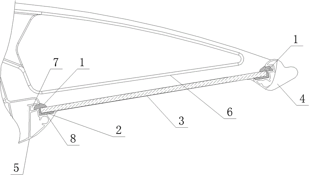
[0035] Example 1, such as figure 1 and figure 2 As shown, the vehicle luggage rack mainly includes:

[0036] A frame structure composed of front profile 4, rear profile 5 and end plates 6 on both sides. The rear profile 5 is installed on the side wall (not shown) inside the passenger room, between the front profile 4 and the rear profile A glass loading plate 3 is embedded.

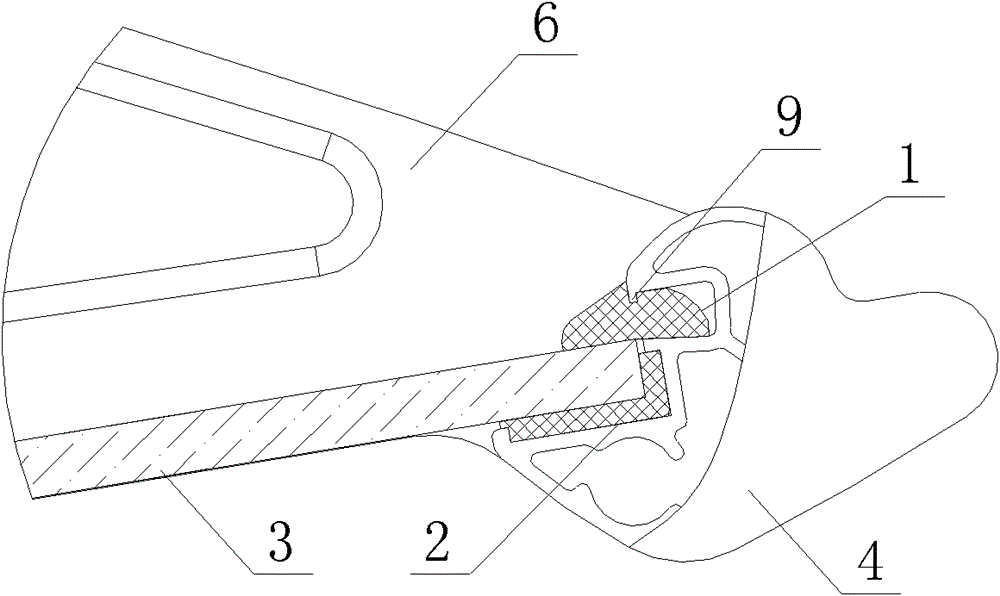
[0037] Wherein, in the cross-sectional structure of the front profile 4 and the rear profile 5, vertically arranged mounting grooves 8 and positioning grooves 7 are symmetrically arranged, such as figure 1 and figure 2 As shown, the side of the positioning groove 7 that is close to the installation groove 8 protrudes from the installation groove 8;

[0038] The front and rear ends of the glass load plate 3 are respectively placed in the installation grooves 8 of the front profile 4 and the rear profile 5;

[0039] Between the front and rear ends of the glass load plate 3 and the installation groove...


PUM


Abstract

The invention discloses a vehicle luggage rack and an installation method, and provides a luggage rack structure which can flexibly fix a glass load bearing board. The glass load bearing board is fixed in a section bar framework of the luggage rack through self rigidity and toughness of an adhesive tape, so that the glass load bearing board can be quickly installed and replaced, and processing efficiency on spot is improved. The vehicle luggage rack comprises a framework structure which is formed by a front section bar, a rear section bar and two side end boards in a connected mode. The luggage rack is installed on a side wall inside a guest room through the two side end boards. The glass load bearing board is installed between the front section bar and the rear section bar in an embedded mode. The section structures of the front section bar and the rear section bar are respectively and symmetrically provided with an installing groove and a locating groove which are perpendicularly arrayed. The front end of the glass load bearing board is placed in the installing groove in the front section bar, and the rear end of the glass load bearing board is placed in the installing groove in the rear section bar. Two groups of rubber pressing strips are respectively installed in the locating grooves in the front section bar and the rear section bar in an embedded mode. The rubber pressing strips are tightly abutted against the edge sides of the glass load bearing board. Therefore, the glass load bearing board is fixed in the section bar framework of the luggage rack in a flexible mode.

Description

technical field [0001] The invention relates to an improvement of a luggage rack structure and an installation and disassembly method applied in a passenger compartment of a rail vehicle, and belongs to the field of mechanical manufacturing. Background technique [0002] As the speed of existing rail vehicles has reached 300 kilometers per hour and above, higher requirements are put forward in terms of the comfort of the riding environment, the convenience of the facilities in the vehicle, and the humanized design. [0003] In order to make the environment in the passenger compartment of the vehicle warm and comfortable, and to allow passengers to check their luggage at any time, the luggage rack in the passenger compartment of rail vehicles is currently equipped with a transparent glass load plate structure. However, a fixed glass plate installation structure is generally adopted at present. If the glass is damaged, the entire luggage rack needs to be disassembled to replac...

Claims


Application Information

Patent Timeline
Patent Type & Authority Patents(China)
IPC IPC(8): B61D37/00
Inventor 潘美风刘世棉
Owner BOMBARDIER SIFANG QINGDAO TRANSPORTATION
Why Eureka
Try Eureka