Drawing die plate for C-shaped silicon core

A template and silicon core technology, which is applied in the field of drawing templates for C-shaped silicon cores, can solve the problems of increased fracture or collapse of silicon cores, large impact of cracks, and inability to grow silicon cores, achieving simple structure and low cost of use , Use the effect of excellent effect

Inactive Publication Date: 2013-06-19
LUOYANG JINNUO MECHANICAL ENG
View PDF12 Cites 1 Cited by
  • Summary
  • Abstract
  • Description
  • Claims
  • Application Information

AI Technical Summary

Problems solved by technology

[0008] At present, there are wire-cut square silicon cores on the market. Due to the wire-cutting process, the crystal is subjected to micro-shocks in diamond wire-cutting, so that there are many tiny cracks in the finished square silicon core that are difficult to detect with the naked eye. The instantaneous impact on the cracks is large, which greatly increases the amount of fractures or collapses during the growth of the silicon cores. In the light cases, the group of silicon cores cannot grow, and in severe cases, the furnace will be shut down. Then, large-diameter silicon cores are used for lap joints. The rapid growth of polycrystalline rods and the improvement of the strength of the silicon core itself have become a technical barrier that is difficult for those skilled in the art to overcome; however, how to increase the diameter of the silicon core is also a long-term demand for those skilled in the art
[0009] The inventors have found through experiments that the C-shaped silicon core can be used to better realize that the silicon core and the cylindrical silicon core can effectively increase the growth area under the same weight. However, there is no C-shaped silicon core at present. Growing Equipment and Templates

Method used


Image

  • Drawing die plate for C-shaped silicon core
  • Drawing die plate for C-shaped silicon core
  • Drawing die plate for C-shaped silicon core

Examples


Embodiment Construction

[0036] The present invention is further described below in conjunction with embodiment; The following embodiment is not for the limitation of the present invention, only as the mode of supporting the realization of the present invention, any equivalent structural replacement within the technical framework disclosed in the present invention, all is the present invention. the scope of protection of the invention;

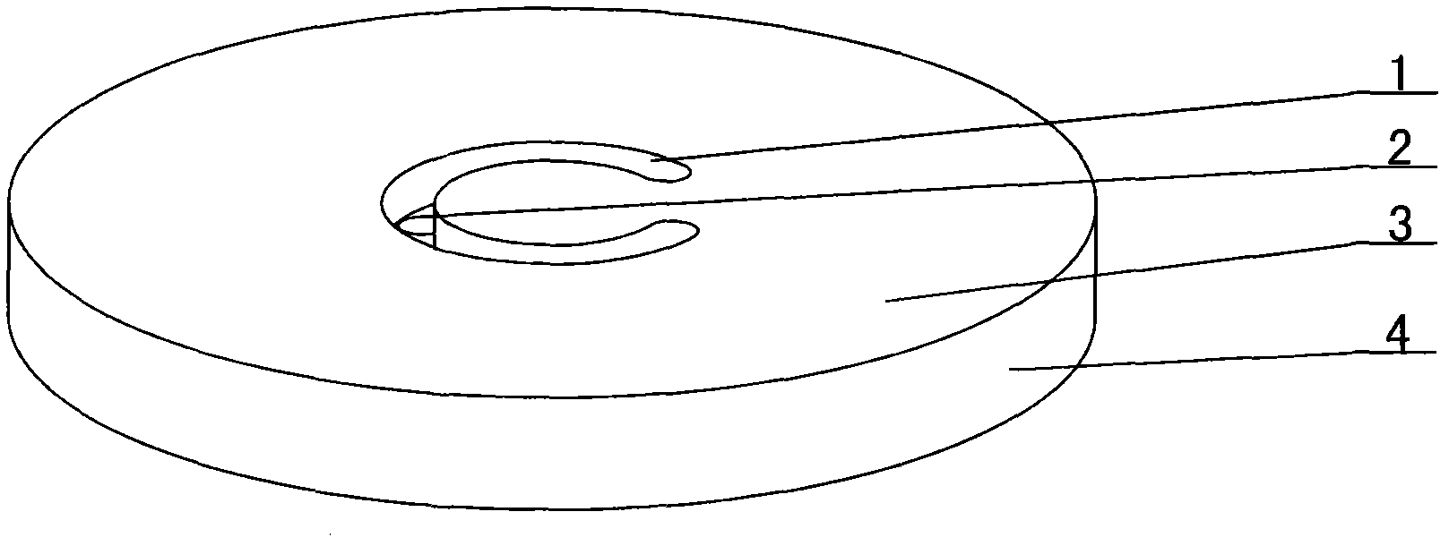
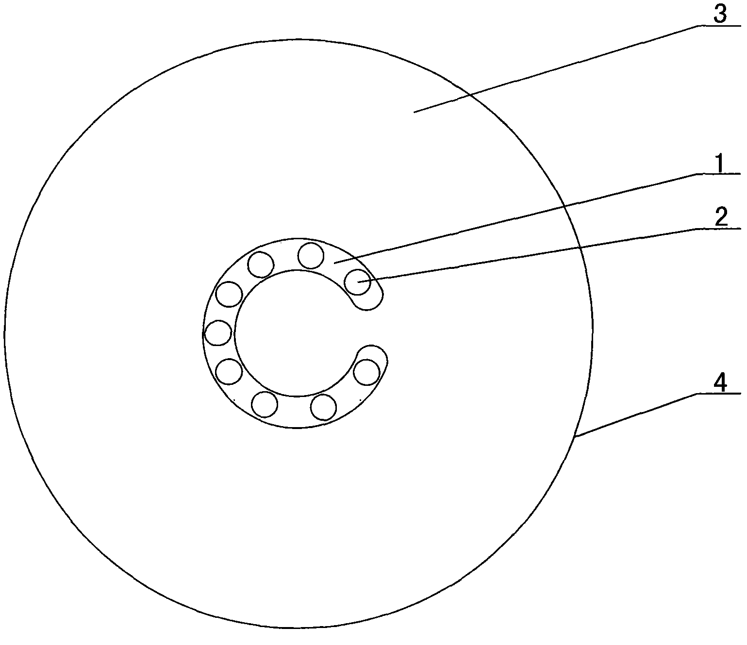
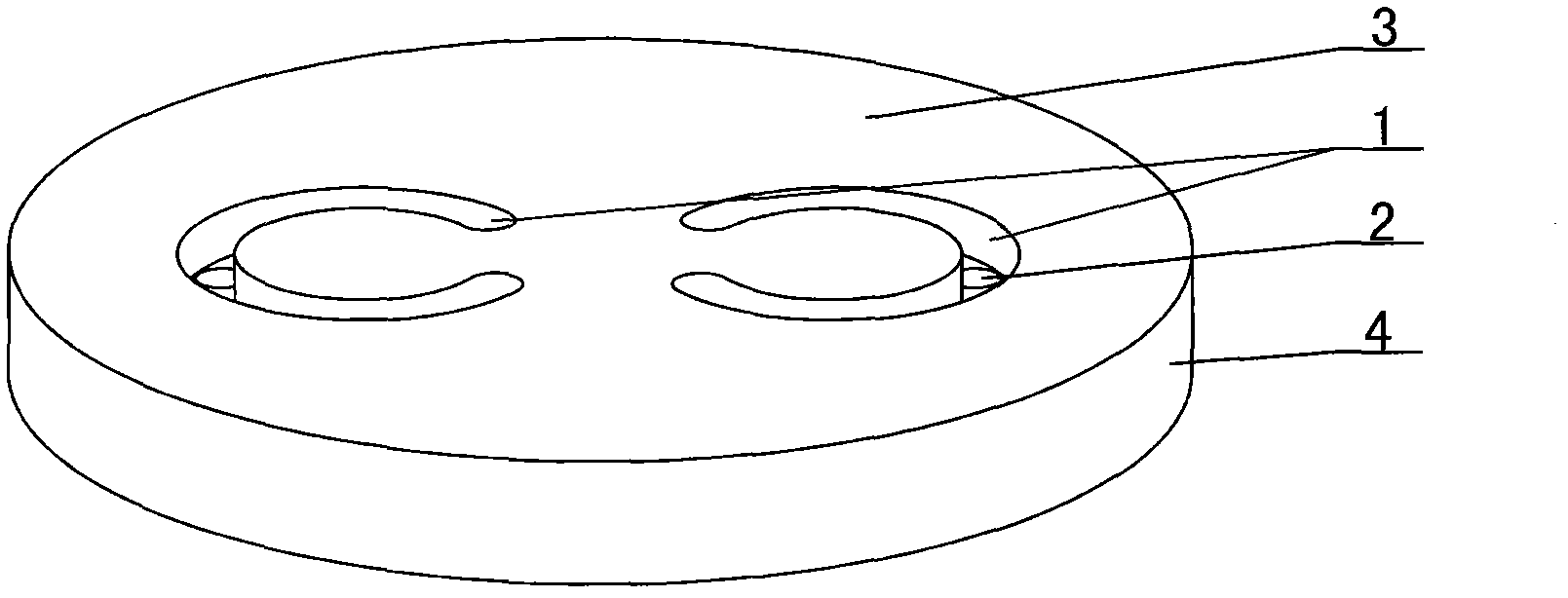
[0037] combined with Figure 1-10 The drawing template of the C-shaped silicon core described in includes a template 4 and a C-shaped groove 1, and a C-shaped groove is arranged on the template, and the bottom of the C-shaped groove 1 is provided with a liquid crystal passage through the bottom of the template 4 ; There is at least one C-shaped groove 1 provided on the template 4, and the bottom of the C-shaped groove is provided with a liquid crystal passage through to the bottom of the template 4; Groove 1, at the bottom of the C-shaped groove 1, a hole correspondi...


PUM


Abstract

The invention discloses a drawing die plate for a C-shaped silicon core, and relates to a die plate. The drawing die plate for a C-shaped silicon core comprises a die plate (4) and a C-shaped groove (1), wherein the C-shaped groove is formed in the die plate, and a crystal solution passage penetrating to the bottom of the die plate (4) is formed in the bottom of the C-shaped groove (1); and the drawing die plate for a C-shaped silicon core disclosed by the invention is used for realizing drawing for the C-shaped silicon core by forming the C-shaped groove in the die plate, enabling the melted crystal solution to enter in the C-shaped groove, and then pulling out the C-shaped silicon core via C-shaped seed crystal. The drawing die plate for the C-shaped silicon core disclosed by the invention is wonderful in conception, simple in structure, and low in use cost; the later-stage use effect of the C-shaped silicon core is superior to the later-stage use effect of the existing cylindrical solid silicon core; and the speed of growing a polycrystalline rod by the C-shaped silicon core is far faster than the speed of growing a polycrystalline rod by the cylindrical solid silicon core. The drawing die plate for the C-shaped silicon core has certain market and application prospects.

Description

【Technical field】 [0001] The invention relates to a template, in particular to a template for drawing a C-shaped silicon core. 【Background technique】 [0002] At present, the amount of silicon cores used in China is very large; the existing silicon cores are produced by zone melting, and high-frequency coils and seed chucks are used in the process to complete the drawing process. The working principle is as follows: When passing high-frequency current to the high-frequency coil, high-frequency induction heating causes the high-frequency coil to generate current to generate magnetic force lines on the raw material rod, and the upper end of the heated raw material rod forms a melting zone, and then inserts the seed crystal into the melting zone, slowly Raising the seed crystal, the molten raw material will follow the seed crystal to rise to form a new columnar crystal, which is the finished product of silicon core or other material crystals. [0003] Then the columnar crystal...

Claims


Application Information

Patent Timeline
Patent Type & Authority Applications(China)
IPC IPC(8): C30B15/24C30B29/06C30B29/66
Inventor 刘朝轩王晨光
Owner LUOYANG JINNUO MECHANICAL ENG
Why Eureka
Try Eureka