
Detachable prestress supporting frame system

A prestressing and support frame technology, which is applied in excavation, construction, and infrastructure engineering, can solve problems such as poor stability of the support structure of the foundation pit, reduce the support density of the supporting beams, and affect the excavation of the foundation pit. The effect of convenient installation, lower engineering cost and lower support density

Active Publication Date: 2013-06-19
DONGTONG ROCK SOIL SCI & TECH HANGZHOU
View PDF8 Cites 46 Cited by
  • Summary
  • Abstract
  • Description
  • Claims
  • Application Information

AI Technical Summary

Problems solved by technology

[0006] The purpose of the present invention is to overcome the fact that a large number of support beams in the existing foundation pit support are distributed in the middle and edge of the foundation pit, and the support density of the support beams is high, which affects the excavation operation of the foundation pit; and the stability of the support structure of the foundation pit is not good. To solve the problem, provide a foundation pit support structure with good stability, and can reduce the support density of the support beam without affecting the strength of the foundation pit support structure, and provide a larger working space for the excavation of the foundation pit. Prestressed Support System

Method used


Image

  • Detachable prestress supporting frame system
  • Detachable prestress supporting frame system
  • Detachable prestress supporting frame system

Examples


Embodiment Construction

[0029] Below in conjunction with accompanying drawing and specific embodiment the present invention is described in further detail:

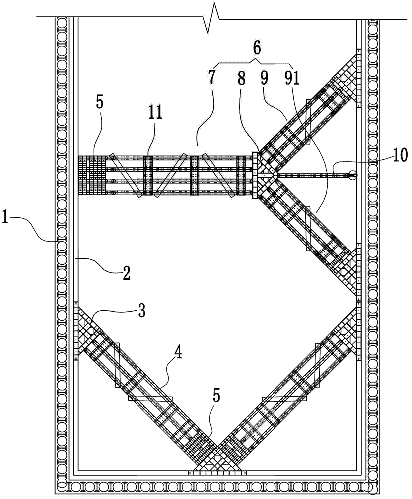
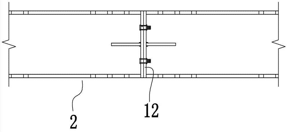
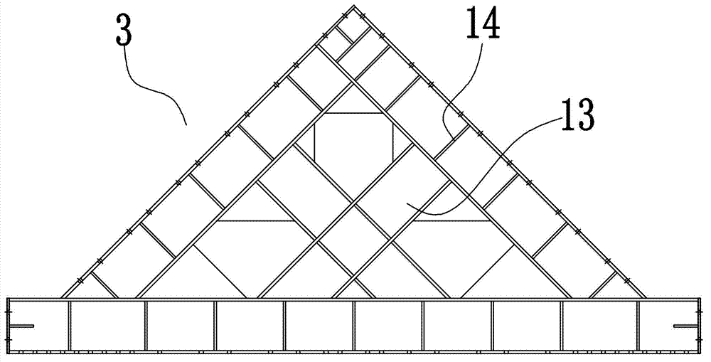
[0030] Such as figure 1 As shown, a detachable prestressed support frame system includes a group of engineering piles 1 arranged around the edge of the foundation pit, and a surrounding beam 2 located inside the engineering piles. Such as figure 2 As shown, the surrounding beam 2 is formed by connecting several I-shaped steels or H-shaped steels. Both ends of each I-beam or H-beam are respectively provided with head plates 12, and the head plates of two adjacent I-beams or H-beams are connected by bolts. There is also a rib plate between the head plate 12 and the web of the I-beam or H-beam. Such as figure 1 , image 3 As shown, some triangular supports 3 are provided on the inner side of the beam 2 around the ring. The triangular support 3 is an isosceles triangle structure and its base and waist are made of I-shaped steel or H-shaped st...


PUM


Abstract

The invention discloses a detachable prestress supporting frame system and aims to provide a supporting frame system which is good in stability of a supporting structure of a foundation pit, can reduce supporting density to a supporting beam and provides larger working space for foundation pit mining operations on the premise of not influencing strength of the supporting structure of the foundation pit. The detachable prestress supporting frame system comprises a group of construction method piles and an enclosure purlin beam. The group of construction method piles are arranged on the edge of the foundation pit. The enclosure purlin beam is arranged on the inner side of the construction method piles. A plurality of triangular supporting members are arranged on the inner side of the enclosure purlin. Angle counter-supporting beams are arranged at the concave corner of the foundation pit. Each angle counter-supporting beam is arranged between two triangular supporting members on two adjacent sides of the concave corner. One end of each angle counter-supporting beam abuts against the side surface of one of the triangular supporting members. A prestress reserved member is arranged between the other end of each angle counter-supporting beam and another triangular supporting member. The prestress reserved member comprises two supporting parts which can be unfolded mutually, one of the two supporting parts abuts against the side surface of the triangular supporting member, and the other supporting part abuts against the end portion of the angle counter-supporting beam.

Description

technical field [0001] The invention relates to a support system, in particular to a detachable prestressed support frame system applied in foundation pits. Background technique [0002] In order to ensure the safety of the underground structure and the surrounding environment of the foundation pit, it is necessary to adopt protective measures such as support and reinforcement on the side wall of the foundation pit and its surroundings. The current foundation pit support system usually includes a group of engineering piles arranged around the edge of the foundation pit, surrounding beams located inside the engineering piles and counter-supporting beams arranged between the surrounding beams. The existing counter-supported beams usually use straight-supported beams to directly support the surrounding beams on opposite sides, so as to strengthen the strength of the support of the foundation pit and control the deformation of the structure. [0003] For example, Chinese Patent...

Claims


Application Information

Patent Timeline
Patent Type & Authority Applications(China)
IPC IPC(8): E02D17/02E02D17/04
Inventor 何一新
Owner DONGTONG ROCK SOIL SCI & TECH HANGZHOU
Learn More