Multi-station full automatic laser power measuring method and system

A technology of laser power and test system, applied in the field of communication, can solve the problems of low efficiency, difficult to find faults in time, easy to affect physical health, etc., so as to reduce the probability of radiation exposure and improve the test efficiency.

Active Publication Date: 2014-11-26
11TH RES INST OF CHINA ELECTRONICS TECH GROUP CORP
View PDF6 Cites 0 Cited by
  • Summary
  • Abstract
  • Description
  • Claims
  • Application Information

AI Technical Summary

Problems solved by technology

According to the usual method, it is often used to test manually with an optical power meter, and the operator must personally monitor the laser
As a result, the operator is in the laser environment for a long time, which is easy to affect the health, and it is difficult to find the fault in time, and the efficiency is low

Method used


Image

  • Multi-station full automatic laser power measuring method and system
  • Multi-station full automatic laser power measuring method and system

Examples


Embodiment 1

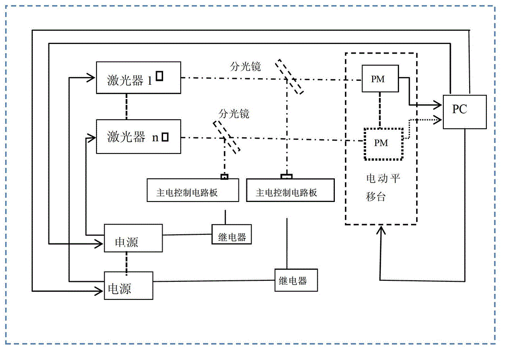
[0036] The embodiment of the present invention provides a multi-station fully automatic laser power testing method, which uses a multi-station fully automatic laser power testing system, see figure 1 , the system includes: one or more lasers, a main electric control circuit board corresponding to the lasers one by one, a beam splitter and a relay;

[0037] The main electric control circuit board receives the laser light of the laser reflected by the corresponding spectroscope, and analyzes and judges the reflected laser light. When it is determined that the reflected laser light is abnormal, the relay will Control the laser power off.

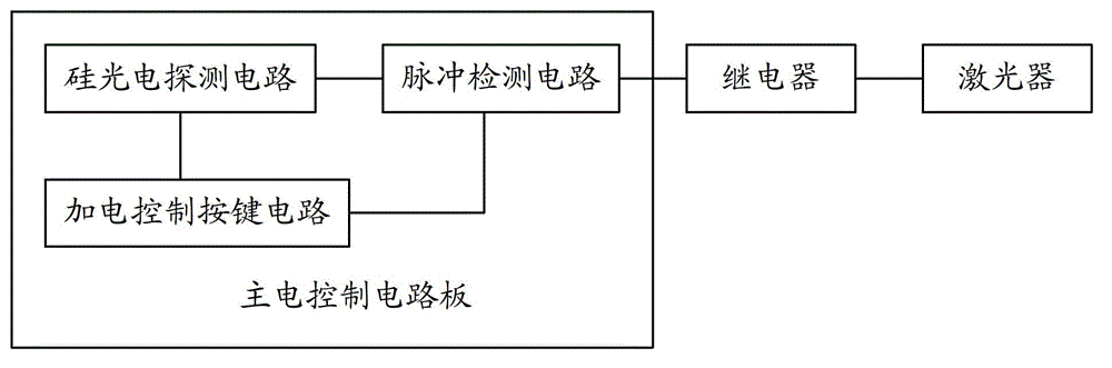
[0038] Wherein, the main electric control circuit board includes: a silicon photoelectric detection circuit and a pulse detection circuit, see figure 2 ;

[0039] The silicon photoelectric detection circuit converts the optical signal of the laser light reflected by the beam splitter into an electrical signal, and sends it to the pulse detec...

Embodiment 2

[0049] The embodiment of the present invention provides a multi-station automatic laser power testing system, see figure 1 , the system includes: one or more lasers, a main electric control circuit board corresponding to the lasers one by one, a beam splitter and a relay;

[0050] The laser is used to emit a laser beam;

[0051] The main electric control circuit board is used to receive the laser light of the laser reflected by the corresponding beam splitter, analyze and judge the laser light, and trigger the relay when it is determined that the laser light is abnormal;

[0052] The relay is used to turn off the power of the laser.

[0053] Preferably, the main electric control circuit board includes: a silicon photodetection circuit and a pulse detection circuit, see figure 2 ;

[0054] The silicon photoelectric detection circuit is used to convert the optical signal of the laser light reflected by the beam splitter into an electrical signal, and send it to the pulse det...


PUM


Abstract

The invention discloses a multi-station full automatic laser power measuring method and a multi-station full automatic laser power measuring system. The multi-station full automatic laser power measuring system comprises one or a plurality of laser devices, and one or a plurality of main electric control circuit boards, beam splitter mirrors and relays which are respectively in one to one correspondence with the laser devices, wherein the main electric control circuit boards receive lasers of the laser devices reflected by the beam splitter mirrors corresponding to the main electric control circuit boards, analyze and judge the reflected lasers, and control a power source of the laser devices to be off through the relays when the reflected lasers are determined to be abnormal. By using the method, an operator does not need to personally monitor the laser devices, and accordingly raying probability of the operator is reduced, and measuring efficiency is improved greatly due to the fact that underreporting probability basically does not exist by analyzing and judging the reflected lasers through the main electric control circuit boards.

Description

technical field [0001] The invention relates to the field of communication technology, in particular to a multi-station fully automatic laser power testing method and system. Background technique [0002] When the laser is built, it is necessary to perform a copy test to eliminate early failures and enter the stable working period of the laser as soon as possible; or in the laser life test test, it is necessary to continuously work on the laser for a long time and record the corresponding data. According to the usual method, the test is often carried out manually with an optical power meter, and the operator must personally monitor the laser. As a result, the operator is in the laser environment for a long time, which is easy to affect the health, and it is difficult to find the fault in time, so the efficiency is low. Contents of the invention [0003] In view of the above analysis, the present invention aims to provide a multi-station automatic laser power testing metho...

Claims


Application Information

Patent Timeline
Patent Type & Authority Patents(China)
IPC IPC(8): G01J1/44
Inventor 朱辰李晋忠张昆张大勇张天华张利明李尧王雄飞
Owner 11TH RES INST OF CHINA ELECTRONICS TECH GROUP CORP
Why Eureka
Try Eureka