Tensile test special fixture used for sheet metal or metal foil and using method

A metal sheet, tensile test technology, applied in the direction of measuring devices, instruments, scientific instruments, etc., can solve the problems of thinning, easy to produce eccentricity, influence of test accuracy, etc., to ensure the effect of experimental accuracy and self-neutrality

Inactive Publication Date: 2013-06-19
JIANGSU UNIV
View PDF11 Cites 25 Cited by
  • Summary
  • Abstract
  • Description
  • Claims
  • Application Information

AI Technical Summary

Problems solved by technology

[0003] The fixture used in the existing tensile testing machine is connected to the sample through a perforated pin, and the tensile testing machine transmits the load to the sample through the perforated pin to perform a one-way or two-way tensile test. The required tensile test can be completed under the condition that the thickness of the material is more than 1mm; when the thickness of the sheet is relatively thin, especially when the thickness of the sheet is less than 0.5mm or even the thickness of the metal foil is less than 0.1mm, the perforation pin is very easy to pass the sample On the other hand, due to the thinning of the sample thickness, the direction of the load applied by the tensile testing machine does not coincide with the geometric center of the sample, which is easy to produce eccentricity, which causes the test to fail. For metal foil samples, due to the scale effect, the influence of errors caused by eccentricity will be more significant

Method used


Image

  • Tensile test special fixture used for sheet metal or metal foil and using method
  • Tensile test special fixture used for sheet metal or metal foil and using method
  • Tensile test special fixture used for sheet metal or metal foil and using method

Examples


Embodiment Construction

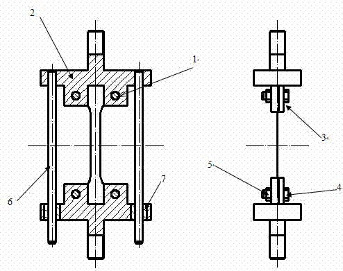
[0019] Depend on figure 2 As shown, the main components of the patent stamping riveting die of the present invention include: each 1 upper and lower chucks, two sets of guide posts 6 guide sleeves 7; The head includes a "T"-shaped clamping element 2, a small clamping element 3, and two sets of bolts 4 and nuts 5; the structure of the lower chuck is the same as that of the upper chuck. The assembly relationship is: the upper and lower "T"-shaped clamping elements 2 are respectively connected to the base of the tensile testing machine through threaded holes 1, and the guide sleeve 7 and the lower "T"-shaped clamping elements 2 are interference fit , There is an interference fit between the guide post 6 and the upper "T" clamping element 2, and a clearance fit between the guide post 6 and the guide sleeve 7.

[0020] The specific assembly process is: first install the guide sleeve with the lower chuck, install the guide post with the upper chuck, and then install the guide slee...


PUM

PropertyMeasurementUnit
thicknessaaaaaaaaaa

Abstract

The invention relates to a tensile test special fixture used for sheet metal or metal foil. The tensile test special fixture comprises an upper clamping head, a lower clamping head, two sets of guide post guide sleeves and threads through which the upper clamping head is connected with a stretcher stretching head base seat, wherein the upper clamping head comprises a T-type clamping component, a small clamping component and two pairs of bolts and nuts, and the upper clamping head is same to the lower clamping head in structure. Through holes are reserved in the upper clamping head and the lower clamping head along the direction parallel to the sample tensile direction, an upper guide sleeve is installed in the lower clamping head through hole, and the upper clamping head through hole is connected with the guide sleeves through guide posts. Bolt holes are reserved in the T-type clamping component and the small clamping component which are in the upper clamping head along the direction perpendicular to the sample tensile direction, and samples are clamped due to the fact that the two groups of bolts penetrate through the reserved holes of the clamping components. The tensile test special fixture used for the sheet metal or the metal foil is simple in structure and convenient to install and clamp, and overcomes various difficulties when the sheet metal and the metal foil are stretched.

Description

technical field [0001] The patent of the present invention relates to the fixture used in the measurement technology, more specifically, the patent of the present invention relates to a special fixture for tensile testing of metal sheets and metal foils. Background technique [0002] Tensile test, also known as tensile test, is a test used to determine a series of properties of materials under tensile load; it is one of the basic methods of material mechanical performance testing, and is mainly used to check whether the material meets the specified standards and Study the performance index of material, such as strength index and plasticity index. [0003] The fixture used in the existing tensile testing machine is connected to the sample through a perforated pin, and the tensile testing machine transmits the load to the sample through the perforated pin to perform a one-way or two-way tensile test. The required tensile test can be completed under the condition that the thic...

Claims


Application Information

Patent Timeline
Patent Type & Authority Applications(China)
IPC IPC(8): G01N3/04
Inventor 陈炜丁毅戴晨雨赵青陈志峰李志朋
Owner JIANGSU UNIV
Why Eureka
Try Eureka