
A coupling alignment device and method for a laser chip and a silicon-based optoelectronic chip

A technology of optoelectronic chips and alignment devices, which is applied in the coupling of optical waveguides, instruments, optics, etc., can solve the problems of low precision, high cost, and low efficiency, and achieve the effects of improving efficiency, simple processing, and simplifying alignment methods

Active Publication Date: 2021-10-15
UNITED MICROELECTRONICS CENT CO LTD
View PDF3 Cites 0 Cited by
  • Summary
  • Abstract
  • Description
  • Claims
  • Application Information

AI Technical Summary

Problems solved by technology

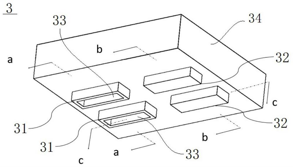
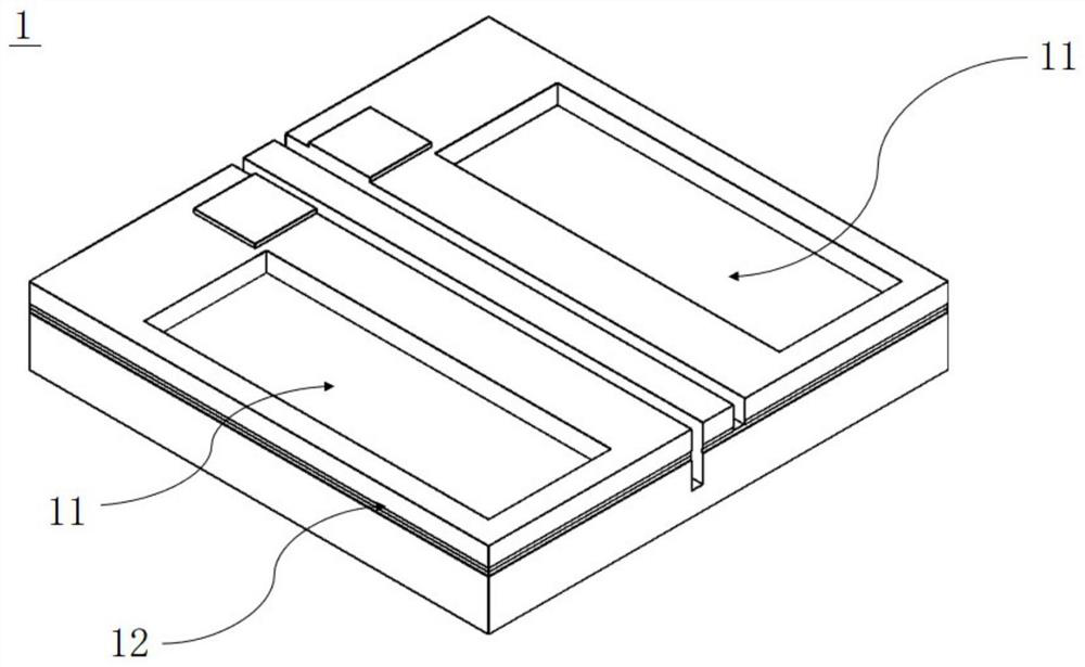
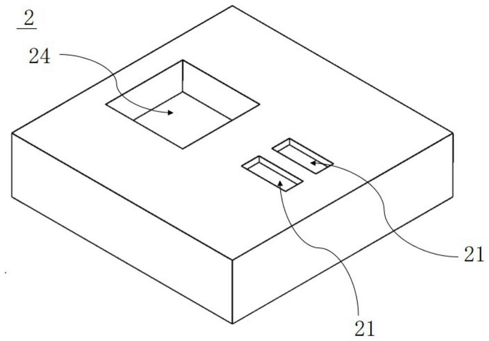
[0006] In order to solve the problems of low precision, low efficiency, and high cost existing in the coupling alignment technology of existing laser chips and silicon-based optoelectronic chips, the present invention innovatively provides a coupling alignment device and method for laser chips and silicon-based optoelectronic chips. Align the contact laser chip and the silicon-based optoelectronic chip with the transfer mold, skillfully transfer the laser chip to the housing chamber of the silicon-based optoelectronic chip, and complete the transfer printing package, which can complete the laser chip and silicon-based optoelectronic chip with high efficiency, high precision and low cost. Coupling and packaging of silicon-based optoelectronic chips, and through innovative design of the alignment shape of bumps and grooves, the work efficiency of coupling alignment is improved, so as to realize batch packaging of laser chips

Method used


Image

  • A coupling alignment device and method for a laser chip and a silicon-based optoelectronic chip
  • A coupling alignment device and method for a laser chip and a silicon-based optoelectronic chip
  • A coupling alignment device and method for a laser chip and a silicon-based optoelectronic chip

Examples


Embodiment Construction

[0055] The device and method for coupling and aligning a laser chip and a silicon-based optoelectronic chip provided by the present invention will be explained and illustrated in detail below in conjunction with the accompanying drawings.

[0056] This embodiment specifically discloses a coupling and alignment device for a laser chip and a silicon-based optoelectronic chip, which realizes the coupling and alignment of a laser chip and a silicon-based optoelectronic chip through a specially designed transfer mold with a simple structure, that is, based on transfer printing and flipping The soldered laser chip and silicon-based optoelectronic chip coupling packaging technology has high alignment accuracy, high efficiency, and low cost, and can realize the scale and mass production of laser chip and silicon-based optoelectronic chip packaging.

[0057] Such as figure 1 As shown, the coupling and alignment device of the laser chip and the silicon-based optoelectronic chip includes...


PUM


Abstract

The invention discloses a coupling alignment device and method for a laser chip and a silicon-based optoelectronic chip. The device includes a transfer mold, and the transfer mold includes a substrate, a first protrusion and a second protrusion, and a through hole is opened on the first protrusion. A hole, the first protrusion is used for snapping into the first groove on the laser chip, and the second protrusion is used for snapping into the second groove on the silicon-based optoelectronic chip. The method includes: etching a first groove on a laser chip, etching a second groove on a silicon-based optoelectronic chip, etching a first protrusion, a second protrusion and a through hole on a transfer mold, The flip-chip welding tip is fixedly connected with the transfer mold, the transfer mold is aligned and contacted with the laser chip, the flip-chip welding tip sucks the laser chip through the through hole, and the laser chip is assembled to the silicon-based optoelectronic chip through the aligned contact of the transfer mold with the silicon-based optoelectronic chip. base optoelectronic chip. The coupling alignment technology of the present invention has high precision, high efficiency and low cost, and can realize scale and mass production.

Description

technical field [0001] The invention relates to the technical field of silicon-based optoelectronic device packaging, and more specifically, the invention relates to a coupling alignment device and method for a laser chip and a silicon-based optoelectronic chip. Background technique [0002] Silicon is an indirect bandgap semiconductor, and its luminous efficiency is not high. Therefore, silicon has always been considered unsuitable for making light source materials. Therefore, for silicon-based optoelectronic technology, the introduction of light sources has become a very important task. [0003] The light source introduction method of silicon-based optoelectronic technology is generally: directly mount the light source on the silicon-based optoelectronic chip, generally mount the laser chip directly on the silicon-based optoelectronic chip by flip chip (Flip chip), and then pass The grating coupling method couples and aligns the waveguide of the laser chip and the waveguid...

Claims


Application Information

Patent Timeline
Patent Type & Authority Patents(China)
IPC IPC(8): G02B6/42
CPCG02B6/4228G02B6/4237G02B6/4245G02B6/4296G02B6/423G02B6/4231
Inventor 彭超冯俊波赵恒
Owner UNITED MICROELECTRONICS CENT CO LTD
Learn More