

System and method for testing fatigue strength of corrugated steel web steel girders
A technology for detecting waveform and fatigue strength, applied in the direction of strength characteristics, using repetitive force/pulsation force to test the strength of materials, measuring devices, etc., can solve the problem of fatigue damage that the local force state does not match the actual situation, and avoid fatigue damage. , easy to replace, widely used effect
- Summary
- Abstract
- Description
- Claims
- Application Information
AI Technical Summary
Problems solved by technology
Method used
Image

Examples
Embodiment 1
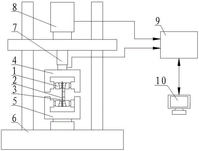
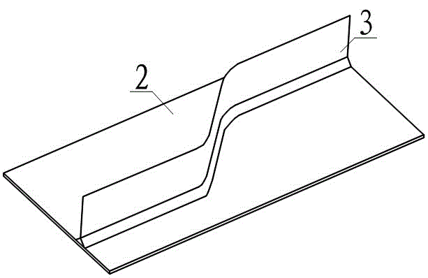
[0024] Such as figure 1As shown, the system for detecting the fatigue strength of corrugated steel web steel girders includes a fatigue testing machine 6, wherein the fatigue testing machine 6 is provided with an upper clamping system 4 and a lower clamping system 5, and the lower clamping system 5 is located on the upper clamping Directly below the system 4, the upper clamping system 4 and the lower clamping system 5 are connected with two chucks 1, the two chucks 1 connected to the upper clamping system 4 have the same level and the clamps of the two chucks 1 The holding ends are facing each other, the area between the two clamps 1 connected by the upper clamping system 4 is the bayonet socket for accommodating the upper end of the steel flange plate 2, and the two clamps 1 connected by the lower clamping system 5 have the same horizontal height and The clamping ends of the two chucks 1 are facing each other, and the area between the two chucks 1 connected by the lower clamp...
Embodiment 2
[0028] This embodiment is further improved on the basis of Embodiment 1. In order to facilitate intelligent control, the system for detecting the fatigue strength of corrugated steel web steel girders in this embodiment also includes an actuator 7, a sensor 8, and a main control box 9 And the computer system 10, wherein, the sensor 8 is a force and displacement sensor, the actuator 7 is connected with the upper clamping system 4, and the main control box 9 is connected with the actuator 7, the sensor 8 and the computer system 10 respectively through three data lines. When the system of this embodiment is used to detect the fatigue strength of the corrugated steel web steel girder, the control and corresponding recording of the applied force are all carried out in the computer system 10. The specific process is: the computer system 10 sends a control signal, and The signal conversion is performed by the main control box 9, and the loading signal is transmitted to the actuator 7 ...
Embodiment 3
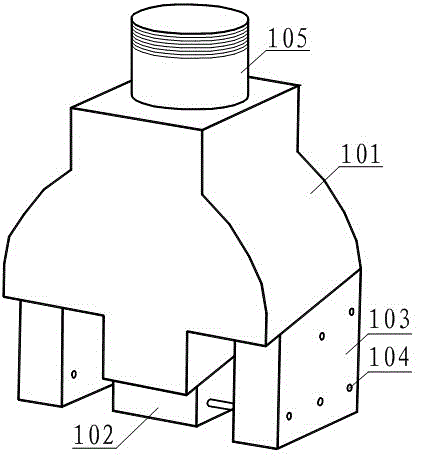
[0030] Such as image 3 As shown, this embodiment has made further improvements on the basis of embodiment 1 or embodiment 2. The chuck 1 of this embodiment includes a chuck body 101, a middle clamping block 102 and a side clamping block 103, wherein the chuck The main body 101, the middle clamping block 102 and the side clamping block 103 all have an end face forming a slope, and the inclination angles of the three slopes are equal, and there is no gap between the slope of the middle clamping block 102 and the slope of the side clamping block 103 and the slope of the chuck body 101 Contact, both the middle clamping block 102 and the side clamping block 103 have a cross-section along the vertical chuck body 101, which is a right-angled trapezoidal shape, and the middle clamping block 102 and the side clamping block 103 are arranged at a certain distance, and the middle clamping block The area between 102 and the side clamping block 103 is a gap for accommodating the straight s...
PUM
 Abstract
Description
Claims
Application Information