Stably-operating adiabatic compressed air storage power generation method and system

A compressed air energy storage and stable operation technology, which is applied to gas turbine devices, machines/engines, liquid variable displacement machinery, etc., can solve problems such as uncontrolled temperature, rise or fall of the temperature of the gas storage chamber, and drop of compressed air temperature , to avoid fatigue damage, stabilize air temperature and improve operating efficiency

Inactive Publication Date: 2014-05-07
NORTH CHINA ELECTRIC POWER UNIV (BAODING)
View PDF5 Cites 10 Cited by
  • Summary
  • Abstract
  • Description
  • Claims
  • Application Information

AI Technical Summary

Problems solved by technology

In the existing compressed air energy storage power generation system, the heat transfer between the gas storage chamber and the surrounding environment only depends on the natural heat dissipation between the wall of the gas storage chamber and the environment, and the variation range of the air temperature in the gas storage chamber is directly related to the pressure change rate of the gas storage chamber. Its temperature is not controlled, poor heat dissipation, especially a short-term rapid rise or fall in the pressure of the gas storage chamber, will cause the temperature of the gas storage chamber to rise or fall rapidly
The frequent rise and fall of the air temperature in the gas storage room will affect the energy storage power consumption and power generation effic

Method used


Image

  • Stably-operating adiabatic compressed air storage power generation method and system
  • Stably-operating adiabatic compressed air storage power generation method and system
  • Stably-operating adiabatic compressed air storage power generation method and system

Examples


Embodiment Construction

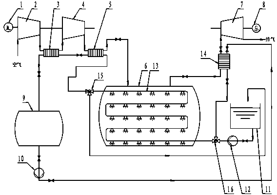
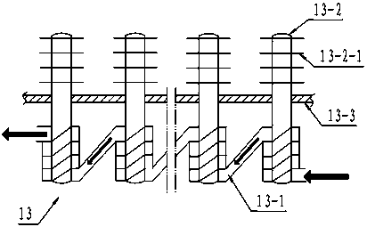
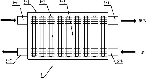
[0019] see figure 1 , the working principle of the present invention is as follows: during the low load period of the power grid, the low-pressure compressor 2 and the high-pressure compressor 4 of the compressed air energy storage power generation system start to work, the compressed air is continuously charged into the air storage chamber 6 through the pipeline, and the air at the outlet of the compressor The temperature, as well as the temperature of the air in the storage chamber, will increase accordingly. At this time, the booster pump 12 starts to work, pumps water out of the reservoir 11, and sends it to the serpentine coil heat pipe heat exchanger 13 through the inlet three-way valve 16 to absorb the heat of compression in the air storage chamber 6; Under the effect of pressure, the final hot water enters the high-pressure countercurrent gas-liquid heat pipe heat exchanger 5 and the low-pressure countercurrent gas-liquid heat pipe heat exchanger 3 through the outlet t...


PUM


Abstract

The invention discloses a stably-operating adiabatic compressed air storage power generation method and system. The technical scheme is as follows: when a power grid is in a valley load, by using a sinuous coil heat pipe exchanger arranged at a gas storage chamber and a countercurrent gas-liquid heat pipe exchanger arranged at an outlet of a gas compressor, through forced circulation, compression heat in a gas compression and energy storage process is absorbed by steps, and the absorbed heat is stored in the heat storage device; and when the power grid is in a peak load, the heat of the heat storage device is released, by using a gas release countercurrent gas-liquid heat pipe exchanger arranged at a turbine motor inlet and the sinuous coil heat pipe exchanger arranged at the gas storage chamber, through forced circulation, the temperature of a gas entering a turbine motor is increased, expansion cold of the gas storage chamber is absorbed, and the temperature of the gas storage chamber is kept relatively stable. According to the stably-operating adiabatic compressed air storage power generation method and system, the compression heat in a gas compression and energy storage process and expansion cold generated in a gas release and power generation process are absorbed by steps, thus a constant temperature of air in the gas storage chamber can be kept, the whole operation efficiency of the system is improved, the safety of the gas storage chamber can be ensured, and continuous and stable operation of a unit is ensured.

Description

technical field [0001] The invention relates to a power generation technology, in particular to a stable operation method and system for adiabatic compressed air energy storage power generation. Background technique [0002] Compressed air energy storage is a large-scale energy storage method with development potential. It has the advantages of fast dynamic response, low cost, and environmental friendliness. When the compressed air energy storage power generation system uses electricity to drive the compressor to compress the air and store it in the air storage chamber, the temperature of the air at the outlet of the compressor and the air temperature in the air storage chamber will increase accordingly. And the faster the air pressure in the gas storage chamber rises, the greater the increase in the temperature of the air in the gas storage chamber. Conversely, during the deflation process of the air storage chamber, the pressure of the air storage chamber will decrease wi...

Claims


Application Information

Patent Timeline
IPC IPC(8): F02C1/00F04B41/02F04B41/06F04B35/04
CPCY02E60/16
Inventor 冉鹏王亚瑟
Owner NORTH CHINA ELECTRIC POWER UNIV (BAODING)
Why Eureka
Try Eureka