Transmission method of a locomotive shaft end speed sensor

A speed sensor, sensor technology, applied in the direction of speed/acceleration/shock measurement, speed/acceleration/shock meter details, instruments, etc. question

Inactive Publication Date: 2015-11-25
GUANGDONG POLYTECHNIC NORMAL UNIV
View PDF3 Cites 0 Cited by
  • Summary
  • Abstract
  • Description
  • Claims
  • Application Information

AI Technical Summary

Problems solved by technology

[0003] The shaft-end photoelectric speed sensors that have been put into use still have problems such as weak reliability, low service life, heavy maintenance and repair workload, and insufficient speed signal detection accuracy.
Through the structural analysis of the current shaft-end photoelectric speed sensor products, and the statistics and research on a large number of maintenance sensor failure phenomena, the main reasons for the poor reliability of the current shaft-end speed sensor are: the service life of the transmission mechanism and devices is low, and the damage is large. The transmission is unreliable and the signal transmission accuracy is insufficient

Method used


Image

  • Transmission method of a locomotive shaft end speed sensor
  • Transmission method of a locomotive shaft end speed sensor
  • Transmission method of a locomotive shaft end speed sensor

Examples


Embodiment Construction

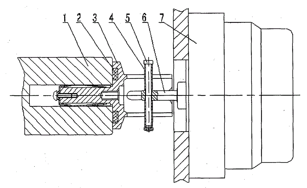
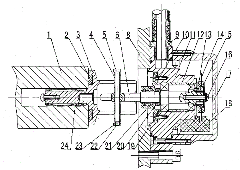
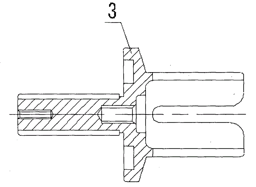
[0010] Referring to the accompanying drawings, an implementation example of a transmission method for a locomotive shaft end speed sensor will be described in detail. The present invention uses the principle of floating transmission to reduce the degree of constraint freedom, adopts rolling contact friction reduction measures, and uses transmission forks, magnetic rings and transmission dials A rod structure, a method and a device for realizing high-reliability transmission under the condition of two degrees of freedom with large floating amount. Including: transmission fork, suction magnetic ring, transmission lever, roller cover, sensor shaft, sensor. drive fork, see figure 2 3 of them, by pulling in the magnetic ring, see figure 2 In 2, connect the transmission fork with the axle end of the locomotive with the drive fork handle, and connect the axle of the locomotive, see figure 2 In 1, the rotation speed is passed through the transmission rod covered with roller sleeves,...


PUM


Abstract

The invention provides a novel transmission method and a device applied to a speed sensor at a shaft end of a locomotive. A floating transmission principle capable of reducing restraint freedom degrees is used, a rolling contact antifriction measurement is adopted, by means of the structure of a transmission fork, a pull-in magnetic ring and a roller transmission lifting lever, the reliable transmission method and the device under conditions of floating amount with two large freedom degrees are achieved. The device comprises the transmission fork, the pull-in magnetic ring, the transmission lifting lever, a transmission lifting lever roller sleeve, a sensor shaft and a sensor. The transmission fork is connected with the shaft end of the locomotive through a fork handle and the pull-in magnetic ring and moves with a shaft of the locomotive, the roller transmission lifting lever is installed at the end portion of the sensor shaft and embedded in a sleeve-shaped fork segment of the transmission fork, and the transmission fork drives the shaft of the locomotive to rotate. Therefore, on the condition that axial bouncing and radial bouncing occur to the shaft of the large-power locomotive relative to a locomotive body, the rotating speed of the shaft of the locomotive is reliably transferred to the sensor shaft. Meanwhile, a three-segment coaxial structure is adopted in the sensor, and rotating precision is effectively improved.

Description

technical field [0001] The invention relates to a transmission method applied to a photoelectric speed sensor at the shaft end of a railway locomotive. The locomotive axle-end photoelectric speed sensor constituted by the method and the device can be widely applied to various models of electric and internal combustion locomotives using the axle-end photoelectric speed sensor. It also has wide applicability to locomotives of various speed series and high-speed railway locomotives currently in use. Background technique [0002] At present, the Shaoshan series and Harmony series electric locomotives and Dongfeng series diesel locomotives currently in use in my country's railway system, in order to detect and effectively control the speed of the locomotive power wheel set and maximize the driving efficiency, generally installed on the axle end of the wheel set Use a shaft end photoelectric speed sensor. With the improvement of train running speed and safety requirements, higher...

Claims


Application Information

Patent Timeline
Patent Type & Authority Patents(China)
IPC IPC(8): G01P1/00
Inventor 屈圭
Owner GUANGDONG POLYTECHNIC NORMAL UNIV
Why Eureka
Try Eureka