Optical cable for remote radio head and manufacturing method of optical cable

A technology of wireless radio frequency and optical cable, which is applied in the direction of fiber mechanical structure, etc., can solve the problems that the bending radius cannot meet the requirements of use, the original performance of optical fiber is difficult to restore, and the investment in stranding equipment is expensive. The effect of low battery

Active Publication Date: 2013-06-19
YANGTZE ZHONGLI OPTICAL FIBER & CABLE (JIANGSU) CO LTD +1
View PDF6 Cites 32 Cited by
  • Summary
  • Abstract
  • Description
  • Claims
  • Application Information

AI Technical Summary

Problems solved by technology

For this reason, domestic research and development in this area have been carried out. The authorized announcement number is CN201689203U, and the name is double-core circular remote optical cable. Double-helix twisting method, this kind of optical cable is easy to cause stress to the relatively fragile optical fiber during production, which leads to an increase in the optical attenuation of the optical cable, and it is difficult to restore the original performance after helical twisting
The authorized announcement number is CN202600198U, and the name is a central beam tube type remote optical cable, which is formed by placing the optical fiber in the central beam tube, then placing a strengthening member outside the central beam tube, and extruding a sheath

Method used


Image

  • Optical cable for remote radio head and manufacturing method of optical cable
  • Optical cable for remote radio head and manufacturing method of optical cable
  • Optical cable for remote radio head and manufacturing method of optical cable

Examples


Embodiment 1

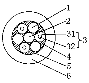
[0038] please see figure 1 , a wireless radio frequency remote optical cable, which includes a central strength member 2, a plurality of filling ropes 1, a plurality of tight sleeve optical fibers 3, surrounding strength members 4, a wrapping layer 5, and a sheath layer 6; it is characterized in that The filling rope and tight-sleeved optical fiber are distributed at intervals around the central strength member and are distributed parallel to the central strength member. The surrounding strength members are located in the cable core gap formed by the central strength member, filling rope, and tight-sleeved optical fiber. The wrapping layer is wrapped in the tight sleeve Outside the optical fiber, the sheath layer is extrusion-coated outside the wrapping layer; the tight-sleeved optical fiber is composed of a natural color or colored optical fiber 32 positioned at the inner layer, and a tight-sleeved layer 32 positioned at the outer layer; the sheath layer is composed of the ...

Embodiment 2

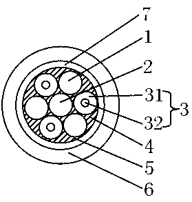
[0040] please see figure 2 , a wireless radio frequency remote optical cable, basically the same as the embodiment 1, the difference is that there is a coating layer 7 between the coating layer and the sheath layer; the coating layer is longitudinally coated or spirally coated on the coating layer External; the material of the cladding layer is water blocking tape or non-woven fabric or polyester tape.

Embodiment 3

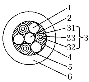
[0042] please see image 3 , a wireless radio frequency remote optical cable, basically the same as the implementation example 1, the difference is that the tight sleeve optical fiber is composed of a natural color or colored optical fiber 32 located in the inner layer, a transition layer 33 located in the middle, and a tight sleeve located outside the transition layer Cover layer 32 constitutes;


PUM

PropertyMeasurementUnit
Diameteraaaaaaaaaa
Diameteraaaaaaaaaa
Diameteraaaaaaaaaa

Abstract

The invention belongs to the technical field of optical cables, and relates to an optical cable for a remote radio head. The optical cable comprises a central reinforcing part, a plurality of fillers, a plurality of tight-buffered optical fibers, peripheral reinforcing parts, a wrapping layer and a sheath layer. The optical cable is characterized in that the fillers and the tight-buffered optical fibers are distributed around the central reinforcing part at intervals and are parallel to the central reinforcing part, the peripheral reinforcing parts are positioned in cable core gaps formed by the central reinforcing part, the fillers and the tight-buffered optical fibers, the wrapping layer wraps the outside of the tight-buffered optical fibers, the sheath layer warps the outside of the wrapping layer in an extruded manner, and the diameter of each filler is larger than or equal to that of each tight-buffered optical fiber. The invention further discloses a manufacturing method of the optical cable. The optical cable mainly solves the problems that tight-buffered optical fibers are easily damaged by a cable twisting mode and are easily punctured by a wrapping layer and the like in the prior art. The optical cable has the main advantages of simple structure, easiness in manufacture, higher heat resistance and small additional attenuation change of the optical fibers used within a wide temperature range.

Description

technical field [0001] The invention belongs to the technical field of optical cables, and in particular relates to an optical cable for wireless radio remote control and a manufacturing method thereof. Background technique [0002] In the base station signal transmission system, the optical cable from the base band unit BBU (Base Band Unit) to the remote radio unit RRU (Remote Radio Unit) is called remote radio optical cable. The optical fiber cable for remote radio unit is mainly used in the local remote at the same site, and the length is usually between 100 meters and 300 meters. With the construction and transformation of the machine station, a large number of optical cables for wireless radio frequency extension are required at home and abroad. For this reason, domestic research and development in this area have been carried out. The authorized announcement number is CN201689203U, and the name is double-core circular remote optical cable. The way of double helix twis...

Claims


Application Information

Patent Timeline
IPC IPC(8): G02B6/44
Inventor 龚建良凌川聂磊张丽芳刘爱华
Owner YANGTZE ZHONGLI OPTICAL FIBER & CABLE (JIANGSU) CO LTD
Why Eureka
Try Eureka