
Semiconductor device safety detection system and semiconductor device safety measuring method

A security detection and semiconductor technology, applied in the direction of electrical testing/monitoring, etc., can solve problems such as frequent operation, power failure of industrial computer, failure to receive operation instructions of industrial computer equipment, etc., and achieve the effect of improving safety

Inactive Publication Date: 2013-06-19
BEIJING NAURA MICROELECTRONICS EQUIP CO LTD
View PDF3 Cites 2 Cited by
  • Summary
  • Abstract
  • Description
  • Claims
  • Application Information

AI Technical Summary

Problems solved by technology

The goal of the PMC program is to improve the efficiency of the industrial computer as much as possible, but the resources of the industrial computer are limited, especially in the process of multi-process chambers, the industrial computer frequently operates the process equipment through the PMC program, once the PMC program runs Abnormal, such as: hardware error, system crash, program error, crash or power failure of the industrial computer, etc., the execution unit will not receive the equipment operation instructions sent by the industrial computer, and if the hardware interlock condition is met at this time, the execution unit will follow the industrial control The equipment operation instructions sent by the computer continue to perform the current operation on the process equipment in the process chamber. At this time, the process equipment loses the control of the industrial computer and is in a state of out-of-control, and the execution unit cannot detect whether the industrial computer is running normally.

Method used


Image

  • Semiconductor device safety detection system and semiconductor device safety measuring method
  • Semiconductor device safety detection system and semiconductor device safety measuring method
  • Semiconductor device safety detection system and semiconductor device safety measuring method

Examples


Embodiment Construction

[0032] In order to enable those skilled in the art to better understand the technical solution of the present invention, the semiconductor device safety detection system and safety detection method provided by the present invention will be described in detail below with reference to the accompanying drawings.

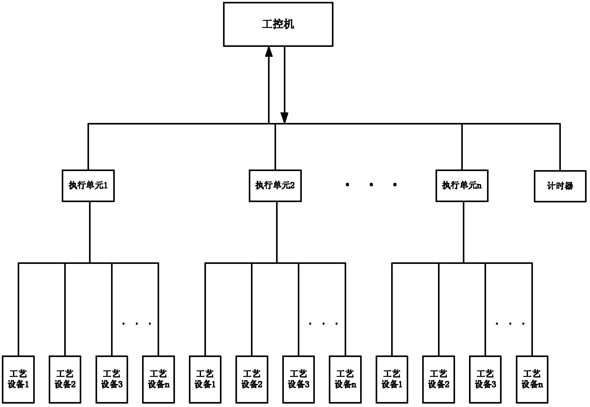
[0033] figure 2 A schematic structural diagram of a semiconductor device safety detection system provided in Embodiment 1 of the present invention, as shown in figure 2 As shown, the semiconductor equipment safety detection system includes: industrial computer, execution unit, process equipment and timer.

[0034] In this embodiment, the semiconductor equipment safety detection system may include multiple execution units, specifically execution unit 1, execution unit 2 to execution unit n, and each execution unit may be used to control multiple process equipment, for example: execution unit 1 is used to Control process equipment 1 to process equipment n.

[0035] Th...


PUM


Abstract

The invention discloses a semiconductor device safety detection system and a semiconductor device safety measuring method. The semiconductor device safety detection system comprises an industrial personal computer, an execution unit processing device and a timer, wherein the industrial personal computer is used for sending detection protocol data to the execution unit according to a set time, the execution unit is used for inquiring whether the detection protocol data sent by the industrial personal computer is received within at the appointed time, if the result is inquired that the detection protocol data sent by the industrial personal computer is not received within the appointed time, the corresponding processing device conducts safety recovery operation, the timer is used for timing the set time and the appointed time, if the execution unit inquires that the detection protocol data sent by the industrial personal computer is not received within the appointed time, the detected result is that the industrial personal computer operates abnormally, and therefore the semiconductor device safety detection system and the semiconductor device safety measuring method enable the execution unit to detect whether the industrial personal computer works normally.

Description

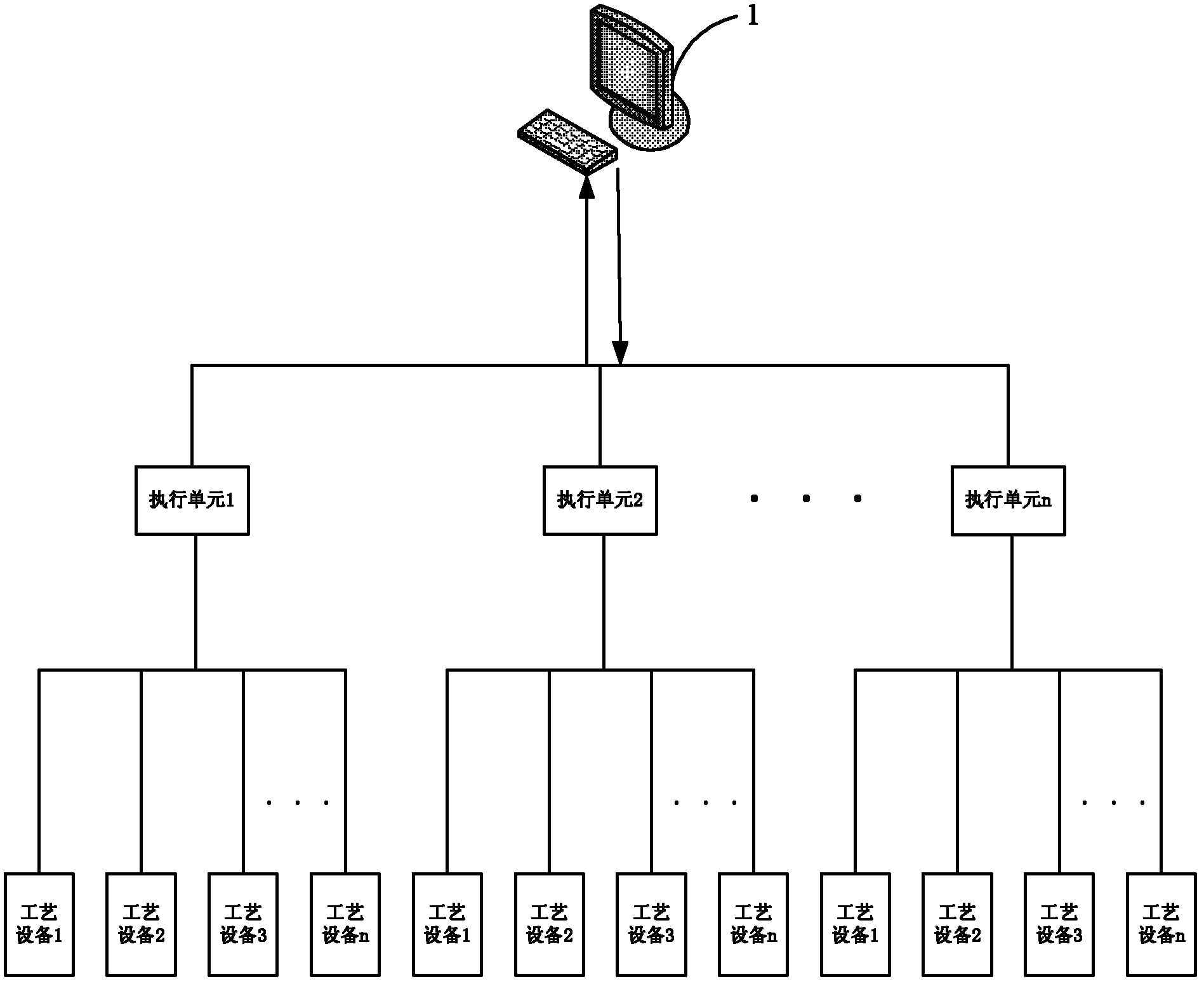
technical field [0001] The invention relates to the technical field of semiconductor device control, in particular to a semiconductor device safety detection system and a semiconductor device safety detection method. Background technique [0002] In the physical vapor deposition (Physical Vapor Deposition, referred to as: PVD) equipment, the industrial computer completes the process control, coordinated control, data display and soft interlock functions through the Process Module Control (hereinafter referred to as: PMC) program, and the execution unit Through the Programmable Logic Controller (hereinafter referred to as: PLC) program to complete the signal conversion, specific equipment operation and hard interlock function, the PLC program has the characteristics of good stability and strong anti-interference ability. figure 1 It is a network topology diagram of a PVD device, such as figure 1 As shown, the PVD equipment adopts a hardware control architecture in which a si...

Claims


Application Information

Patent Timeline
IPC IPC(8): G05B23/02
Inventor 李福增
Owner BEIJING NAURA MICROELECTRONICS EQUIP CO LTD
Learn More