Light emitting diode display panel and control method thereof

A technology of light-emitting diodes and display panels, applied to static indicators, instruments, etc., can solve problems such as poor display uniformity and inconsistent brightness, and achieve the effects of increasing operating voltage, reducing line loss, and reducing control current

Inactive Publication Date: 2013-06-19
苏州微体电子科技有限公司
View PDF0 Cites 1 Cited by
  • Summary
  • Abstract
  • Description
  • Claims
  • Application Information

AI Technical Summary

Problems solved by technology

Therefore, due to the different ohmic contact internal resistance and the inconsistency caused by the LED manufacturing process, the brightness of each LED is inconsistent, resulting in poor display uniformity

Method used


Image

  • Light emitting diode display panel and control method thereof
  • Light emitting diode display panel and control method thereof
  • Light emitting diode display panel and control method thereof

Examples


Embodiment 1

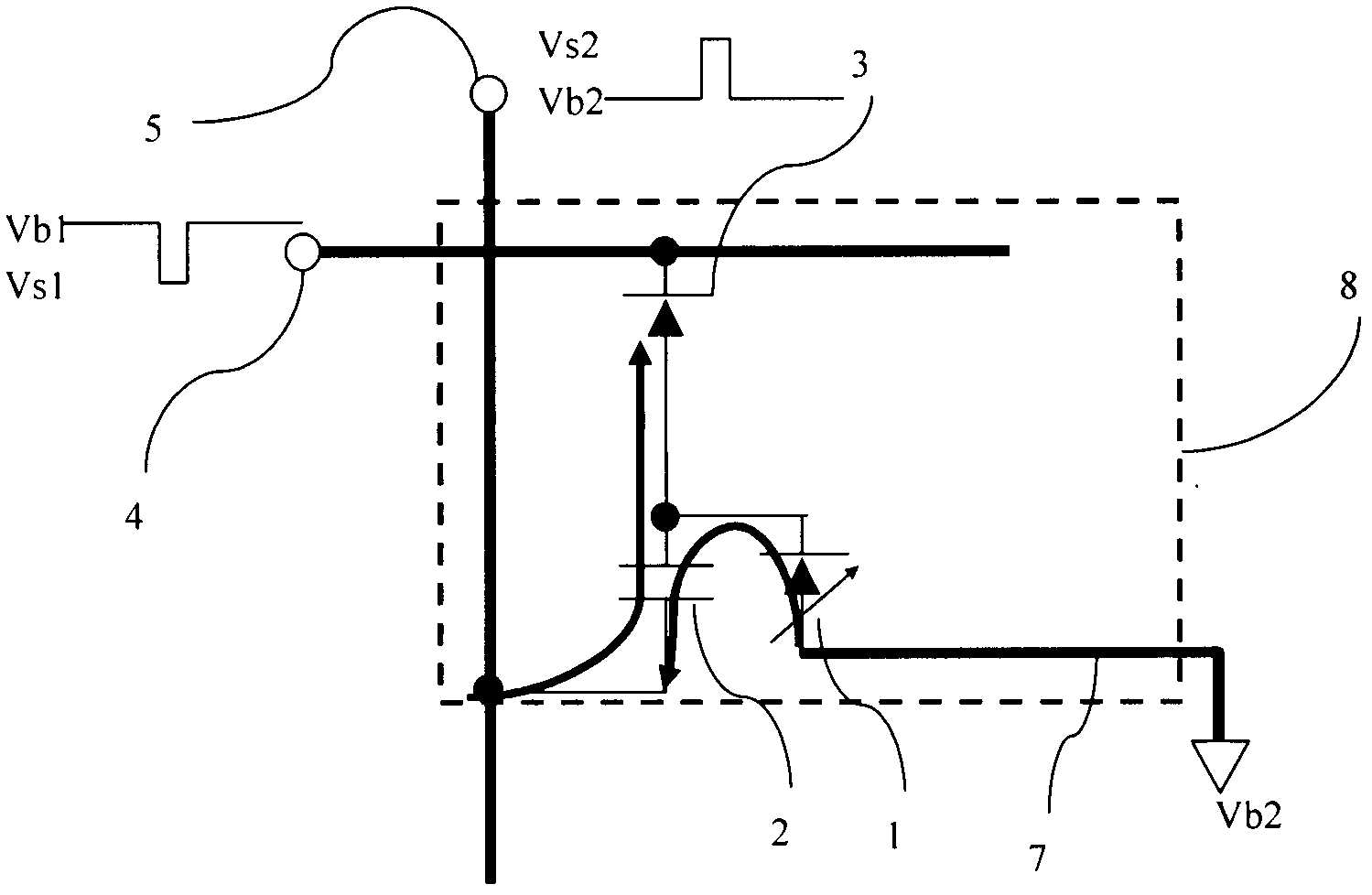
[0026] as attached figure 1 A light-emitting diode display panel shown, each pixel 8 includes a first electrode 4, a display capacitor 2 connected to the first electrode 4, a diode 3 connected to the display capacitor 2, and a light-emitting diode 1 connected to the diode 3 The second electrode 5 and the third electrode 7 connected to the other end of the light-emitting diode 1; a one-way charging circuit composed of the diode 3 and the display capacitor 2, and a discharge display circuit composed of the display capacitor 2 and the light-emitting diode 1, relative to the display Capacitor 2, diode 3 and light-emitting diode 1 are opposite in polarity, as attached figure 1 As shown, it is also possible to change the polarity of the diode 3 and the light-emitting diode 1 at the same time.

Embodiment 2

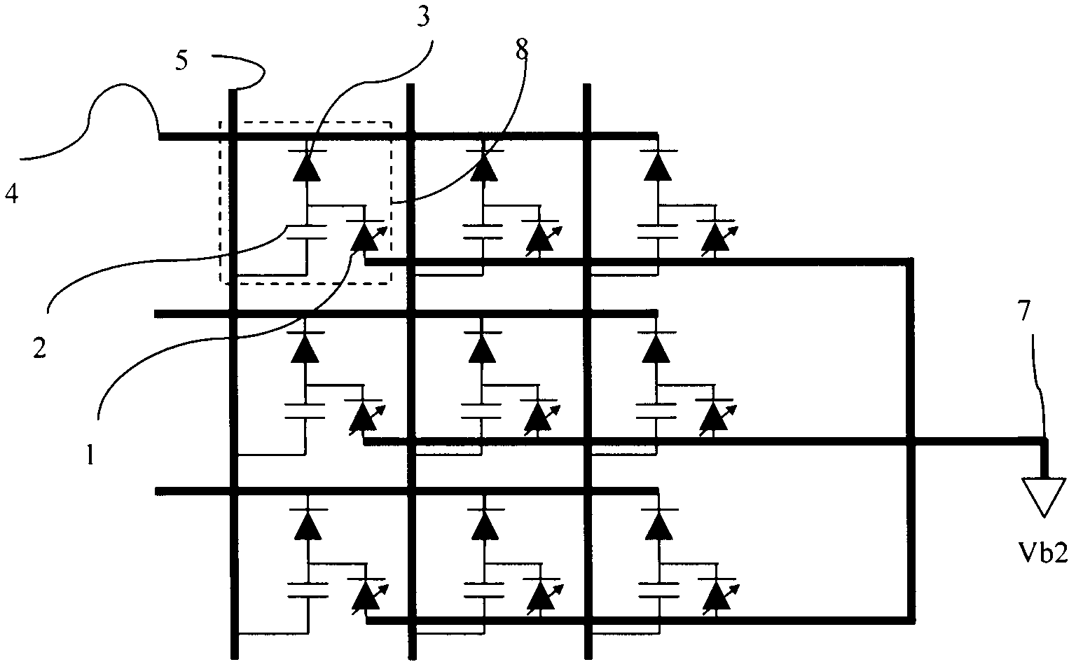
[0028] as attached figure 2 A light-emitting diode display panel shown, each pixel 8 includes a first electrode 4, a display capacitor 2 connected to the first electrode 4, a diode 3 connected to the display capacitor 2, and a light-emitting diode 1 connected to the diode 3 Composed of the second electrode 5, it is characterized in that the other ends of the light emitting diodes 1 of all pixels are connected together and connected to the third electrode 7; with respect to the display capacitor 2, the polarity of the diode 3 and the light emitting diode 1 is opposite, and can be as attached figure 2 As shown, the polarity of diode (3) and LED 1 can also be changed at the same time.

Embodiment 3

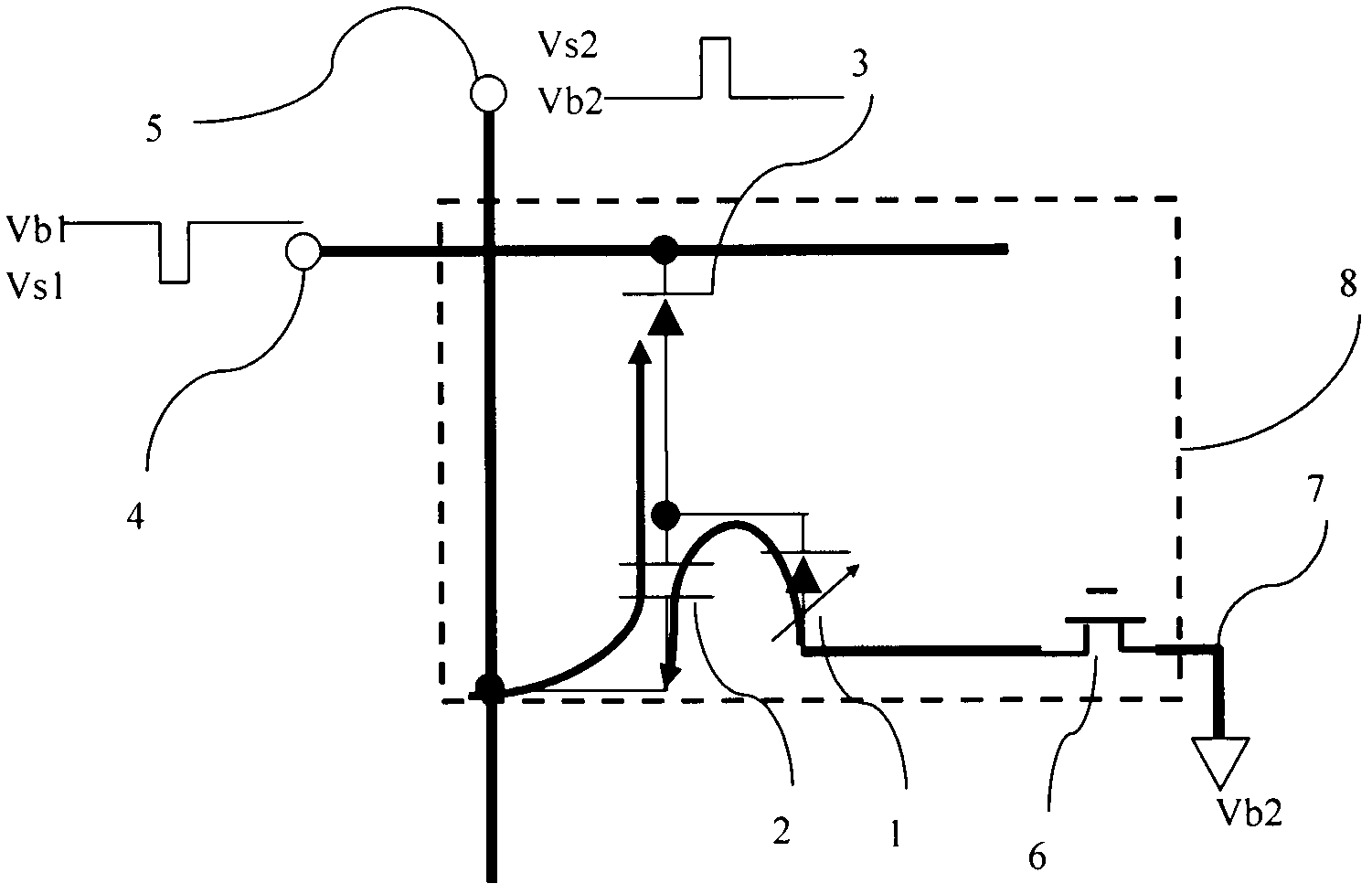
[0030] as attached image 3 A light-emitting diode display panel shown, each pixel 8 includes a first electrode 4, a display capacitor 2 connected to the first electrode 4, a diode 3 connected to the display capacitor 2, and a light-emitting diode 1 connected to the diode 3 The second electrode 5 of the light-emitting diode 1, the switch tube 6 connected to the other end of the light-emitting diode 1, and the third electrode 7 connected to the switch tube 6; a one-way charging circuit is composed of the diode 3 and the display capacitor 2, and the display capacitor 2, the light-emitting The diode 1 and the display switch 6 form a discharge display circuit. Compared with the display capacitor 2, the polarity of the diode 3 and the light-emitting diode 1 are opposite. image 3 As shown, it is also possible to change the polarity of the diode 3 and the light-emitting diode 1 at the same time.


PUM


Abstract

The invention discloses a light emitting diode (LED) display panel and a control method thereof. The LED display panel is composed of a great deal of pixel. Each pixel comprises a LED, a display capacitance, a diode, a first electrode, a second electrode and a third electrode. In the control method of the LED display panel, by means of charging the capacitance arranged inside each pixel, the LED in series then can be used for forming capacitance discharging current to enable the LED to give out light. A suitable capacitance value can be chosen to enhance the working voltage of a control circuit, lower control current and reduce line loss caused by large current control and the pressure of control source.

Description

technical field [0001] The invention relates to a light emitting diode (LED) display panel and a control method thereof. Background technique [0002] Light-emitting diode (LED) display has the advantages of super large screen, high brightness display, fast response speed, and bright colors, which makes it an indispensable place in the field of super large size, indoor and outdoor displays, but due to manufacturing process problems, LED units The inconsistency among them is serious. In order to solve the inconsistency problem, each LED unit must be independently controlled and corrected, and the control cost is high; because LED is a low-voltage, high-current device, and high current requires high power supply, the circuit The loss is large. [0003] In view of the above problems existing in current LED displays, the present invention relates to a light emitting diode (LED) display panel and a control method thereof. The LED display panel proposed by the present invention ...

Claims


Application Information

Patent Timeline
IPC IPC(8): G09G3/32
Inventor 施金伟
Owner 苏州微体电子科技有限公司
Why Eureka
Try Eureka