Check patentability & draft patents in minutes with Patsnap Eureka AI!

rotating electrical machine

A technology of rotating motors and rotating shafts, which is applied in the direction of electrical components, electromechanical devices, electric components, etc., which can solve the problems of high corrosion and aging of casing parts, and reduced water resistance, and achieve excellent water resistance effects

Inactive Publication Date: 2016-04-13
YASKAWA DENKI KK
View PDF6 Cites 0 Cited by
  • Summary
  • Abstract
  • Description
  • Claims
  • Application Information

AI Technical Summary

Problems solved by technology

[0006] In this case, if the aforementioned connecting portion is provided on the side of the rotating electrical machine, the connecting portion is intensively exposed to the cutting fluid, thereby making the possibility of causing corrosion and aging of the bushing parts high
That is, there is a possibility that the waterproofness may be lowered

Method used


Image

  • rotating electrical machine
  • rotating electrical machine
  • rotating electrical machine

Examples


Embodiment Construction

[0050] Hereinafter, embodiments of the rotating electric machine disclosed in the present application will be described in detail with reference to the drawings. In addition, this invention is not limited to embodiment shown below.

[0051] In addition, in the following, a rotating electric machine used as a spindle motor of a machine tool that performs cutting in an atmosphere containing a large amount of mist cutting fluid will be described as an example.

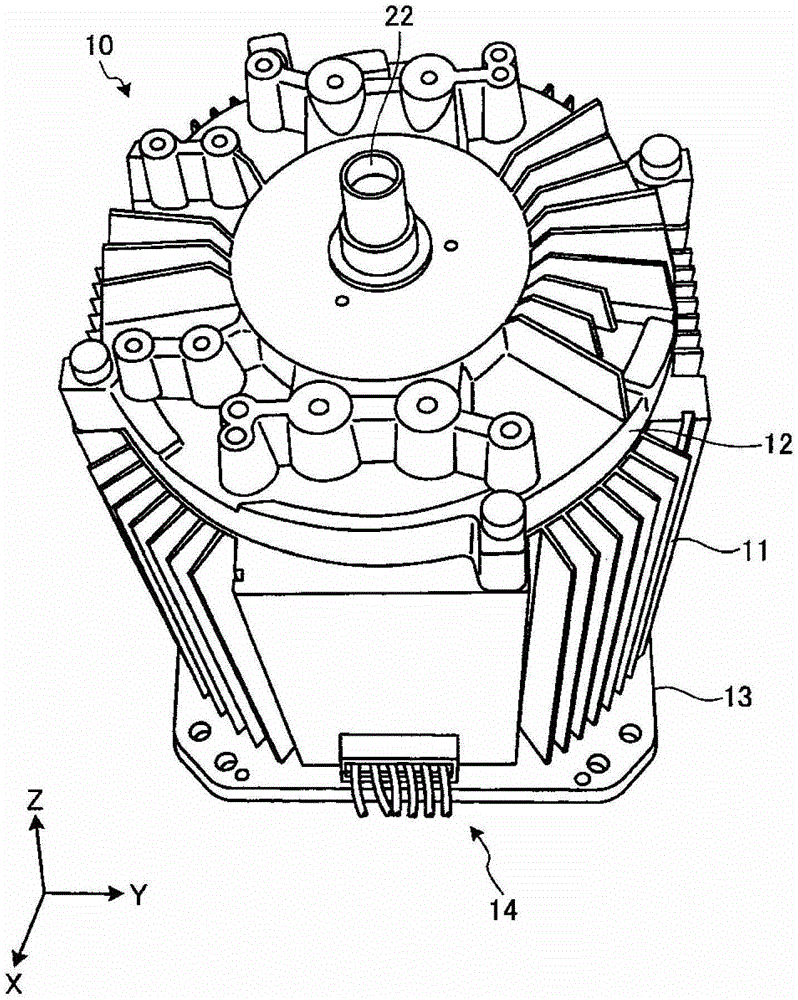
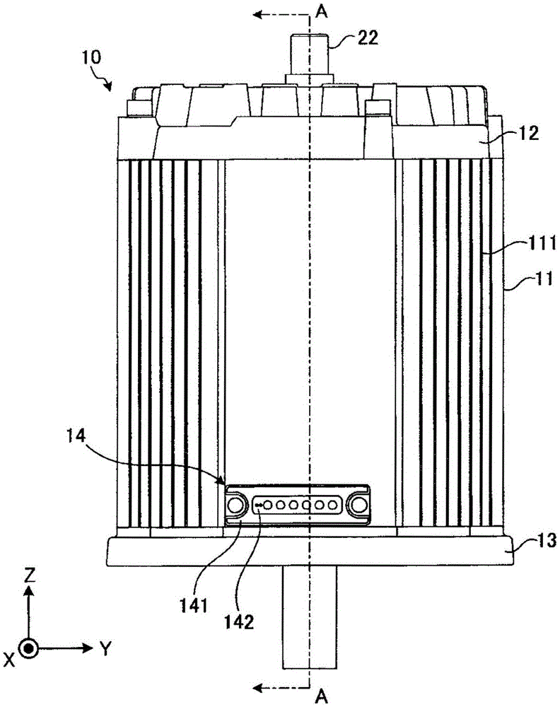
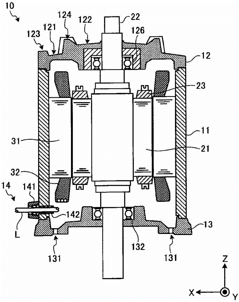
[0052] First, use figure 1 A schematic configuration of the rotating electric machine according to the embodiment will be described. figure 1 It is a perspective view of the rotating electrical machine 10 of embodiment.

[0053] And, for ease of understanding, the figure 1 , illustrates a three-dimensional Cartesian coordinate system including a Z-axis with a vertically upward direction as a positive direction and a vertically downward direction (ie, “vertical direction”) as a negative direction. In other drawings use...


PUM


Abstract

The invention provides a rotation motor capable of expressing excellent waterproof property. The rotation motor comprises a frame and a support. The frame is proximately a cylinder shape with an opening port on a side wall and is used for containing a rotor and a stator. The support is mounted on the frame and is for supporting a rotation shaft of the rotor. The support is provided with an outer periphery vertically arranged along an arranging direction of the opening port if observed from a rotation shaft direction. The outer periphery of the support comprises a cone surface facing a radial outside direction to form a slope.

Description

technical field [0001] The disclosed embodiments relate to rotating electric machines. Background technique [0002] Conventionally, a rotating electric machine used as a spindle motor of a machine tool is known. In many cases, such a rotating electric machine is required to have high water resistance, for example, when it is placed in an atmosphere containing a large amount of mist-like cutting fluid during cutting. [0003] Therefore, a sleeve member such as a waterproof connector (see Patent Document 1) that fills the gap with the elasticity of an elastic material is used at a portion where a gap is likely to occur in the rotating electric machine, such as a connection portion of a lead wire. [0004] Patent Document 1: Japanese Patent Laid-Open No. 2000-200650 [0005] However, there is still room for further improvement in terms of exhibiting excellent waterproofness in conventional rotating electrical machines. For example, the aforementioned misty cutting fluid may...

Claims


Application Information

Patent Timeline
Patent Type & Authority Patents(China)
IPC IPC(8): H02K5/10
Inventor 下野博史井上猛贵
Owner YASKAWA DENKI KK
Features
  • R&D
  • Intellectual Property
  • Life Sciences
  • Materials
  • Tech Scout
  • Unparalleled Data Quality
  • Higher Quality Content
  • 60% Fewer Hallucinations
Learn More