Control circuit for three-phase high power factor rectifier

A high power factor, control circuit technology, applied in the field of rectifiers, can solve the problems of complex control, poor control effect, and difficult to achieve

Inactive Publication Date: 2013-06-19
YANGZHOU XINHAO HEAVY MACHINERY
View PDF3 Cites 14 Cited by
  • Summary
  • Abstract
  • Description
  • Claims
  • Application Information

AI Technical Summary

Problems solved by technology

[0005] Aiming at the shortcomings in the prior art that the control effect is poor when the control is relatively simple and the control is complicated and difficult to realize when the effect is good, the present invention provides a control circuit for a three-phase high power factor rectifier, which can realize three-phase high power factor rectifier Power factor rectification, can obtain higher precision steady-state output voltage, strong anti-interference ability, and easy to implement

Method used


Image

  • Control circuit for three-phase high power factor rectifier
  • Control circuit for three-phase high power factor rectifier
  • Control circuit for three-phase high power factor rectifier

Examples


Embodiment

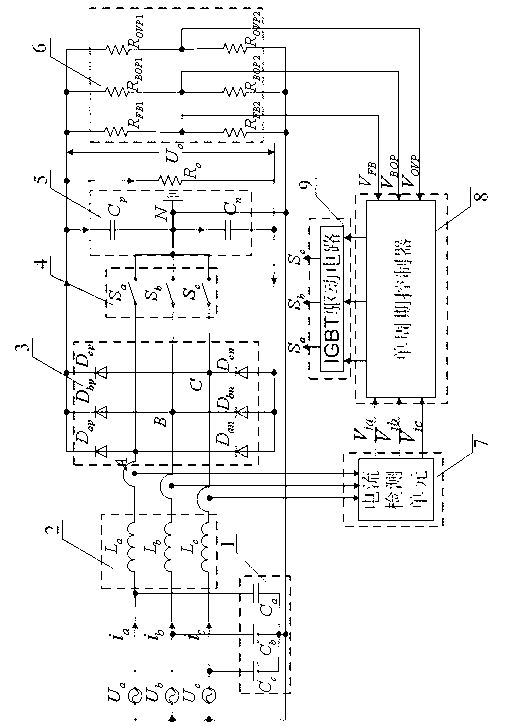
[0037] The control circuit of the three-phase high power factor rectifier of the present embodiment, such as figure 1 As shown, it includes input high-frequency filter circuit 1, three-phase input inductor 2, three-phase rectification circuit 3, switch tube power circuit 4, output rectification filter circuit 5, voltage division detection circuit 6, input current detection unit 7, single-cycle A controller 8 and a switch tube drive circuit 9.

[0038] The input high-frequency filter circuit 1 includes three ceramic capacitors C with a withstand voltage of 630V and a size of 2.2uF a 、C b and C c , C a 、C b and C c One end of the grid is respectively connected to the grid A-phase voltage input terminal, the grid B-phase voltage input terminal and the grid C-phase voltage input terminal, and the other end is connected to the neutral wire of the three-phase four-wire electricity at the same time, and the neutral wire is grounded. The three-phase input inductor 2 includes th...


PUM


Abstract

The invention discloses a control circuit for a three-phase high power factor rectifier, and belongs to the field of electrical control. The control circuit comprises an input high-frequency filter circuit, a three-phase input inductor, a three-phase rectifier circuit, a switch tube power circuit, an output rectifier filter circuit, a voltage-dividing detection circuit, an input current detection unit, a single cycle controller and a switch tube driving circuit. A three-phase high power factor can be rectified, high-precision stable output voltage can be obtained, and interference resistance is high.

Description

technical field [0001] The invention relates to the field of electrical control, and more specifically relates to a rectifier which uses a single-cycle single-phase PFC chip to control a decoupled three-phase circuit and realizes three-phase high power factor input. Background technique [0002] With the development of the national economy, there are more and more various electrical equipment. Since the input of most electrical equipment adopts non-controllable rectification, the harmonic content of the input terminal current of electrical equipment is very high, which brings a lot of "harmonic pollution" to the power grid and increases the loss of the power grid. In order to reduce the harmonic pollution and electromagnetic interference of the device to the power grid, a corresponding harmonic suppression method and power factor correction circuit are proposed. Therefore, it is necessary to add a power factor correction (Power Factor Correction, PFC) device to the input of ...

Claims


Application Information

Patent Timeline
Patent Type & Authority Applications(China)
IPC IPC(8): H02M7/217H02M1/42
CPCY02B70/10
Inventor 方炜王智刘晓东
Owner YANGZHOU XINHAO HEAVY MACHINERY
Why Eureka
Try Eureka