Backlight device, liquid-crystal display device, and lens

A technology of liquid crystal display devices and backlight devices, which is applied in the directions of display devices, lenses, condenser mirrors, etc., can solve the problems that cannot be realized cheaply, and achieve the effect of simple structure and low cost

Inactive Publication Date: 2013-06-19
PANASONIC CORP
View PDF12 Cites 4 Cited by
  • Summary
  • Abstract
  • Description
  • Claims
  • Application Information

AI Technical Summary

Problems solved by technology

By using many light-emitting diodes, uniform brightness can be obtained on the surface of the backlight, but there is a problem that it cannot be realized at a low cost due to the need for many light-emitting diodes

Method used


Image

  • Backlight device, liquid-crystal display device, and lens
  • Backlight device, liquid-crystal display device, and lens
  • Backlight device, liquid-crystal display device, and lens

Examples


Embodiment Construction

[0031] Hereinafter, a backlight device and a liquid crystal display device using the backlight device according to an embodiment of the present invention will be described with reference to the drawings.

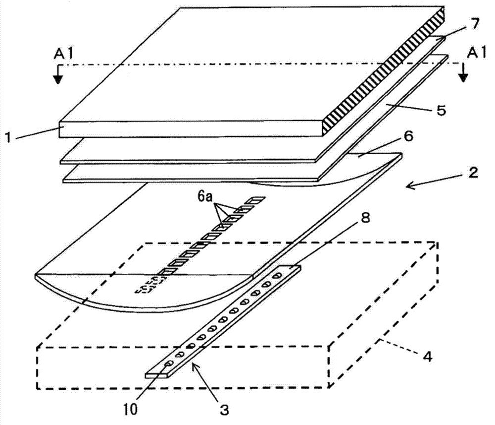
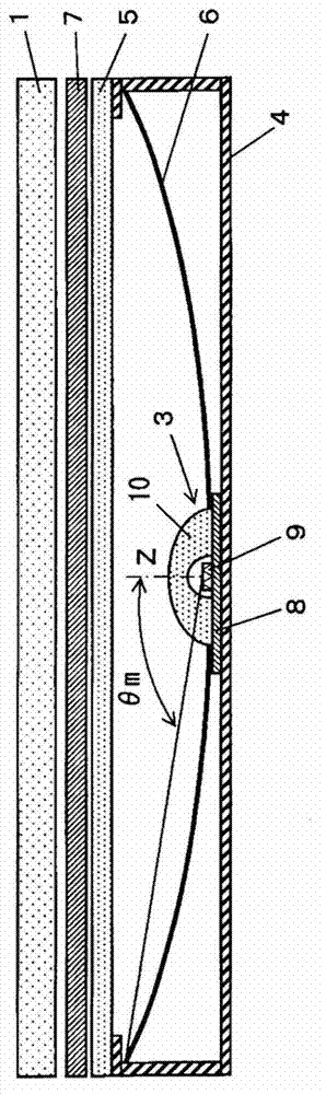
[0032] figure 1 It is an exploded perspective view showing an overall schematic structure of a liquid crystal display device using a backlight device according to an embodiment of the present invention, figure 2 so figure 1 The sectional view of A1-A1 line truncation.

[0033] Such as figure 1 , figure 2 As shown, the liquid crystal display device includes: a rectangular flat plate-shaped, transmissive liquid crystal display panel 1; .

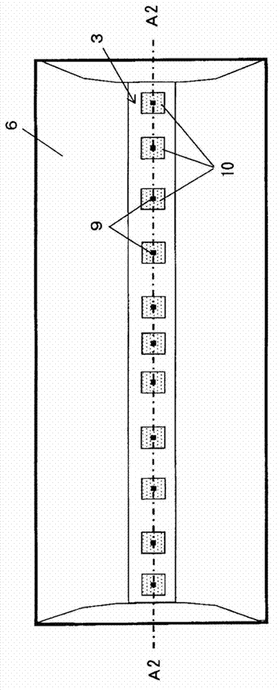
[0034] The backlight device 2 has: a light source unit 3 arranged linearly along the longitudinal direction of the liquid crystal display panel 1 to face the center of the liquid crystal display panel 1; a rectangular parallelepiped frame 4 for accommodating the light source unit 3; plate 5, the diffusion plate is arranged to cover t...


PUM

PropertyMeasurementUnit
refractive indexaaaaaaaaaa

Abstract

A backlight device (2) provided with: a light-source unit (3) comprising a plurality of light-emitting diodes (9) and lenses (10) that spread the light from said light-emitting diodes (9); a housing (4) that contains said light-source unit (3); a diffusion panel (5) disposed so as to cover an opening (6a) in said housing (4); and a reflective sheet (6) that reflects light from the light-source unit (3) towards the diffusion panel (5). The light-emitting diodes (9) are arranged in one or more rows in the middle of the light-source unit (3). The lenses (10) in the light-source unit (3) have input surfaces (11) onto which the light from the light-emitting diodes (9) is incident and output surfaces (12) from which the incident light, having been spread out, is transmitted. The shape of the projection of each input surface (11) from the top surface is made elliptical about the optical axis (Z) by means of a continuous concave surface.

Description

technical field [0001] The invention relates to a backlight device, a liquid crystal display device and a lens using a light emitting diode as a light source. Background technique [0002] In conventional backlight devices for large liquid crystal display devices, cold cathode tubes are mostly arranged directly below the liquid crystal panel, and these cold cathode tubes are used together with components such as a diffuser plate and a reflector plate. Also, in recent years, light emitting diodes have been used as light sources of backlight devices. Efficiency of light-emitting diodes has improved in recent years, and they are expected to replace fluorescent lamps as light sources that consume less power. Furthermore, as a light source for a liquid crystal display device, the power consumption of the liquid crystal display device can be reduced by controlling the light and shade of the light emitting diodes according to the image. [0003] In a liquid crystal display device...

Claims


Application Information

Patent Timeline
Patent Type & Authority Applications(China)
IPC IPC(8): F21S2/00F21V5/04F21V5/08G02B3/00G02F1/13357H01L33/58F21Y101/02
CPCG02B19/0028G02B19/0066G02F1/133603G02F1/133605G02F1/133606G02F1/133607G02F1/133602G09F13/14
Inventor 松木大三郎林克彦长谷川贤治山口博史
Owner PANASONIC CORP
Why Eureka
Try Eureka