
Thermal paste smearing apparatus

A heat dissipation paste and heat sink technology, which is applied in spraying devices, devices for coating liquid on surfaces, coatings, etc., can solve the problem of low efficiency and quality of heat dissipation paste application, affecting the performance and stability of electronic components, and application of heat dissipation paste Quantity and thickness are difficult to grasp and other issues

Active Publication Date: 2013-06-26
NORTH CHINA UNIVERSITY OF SCIENCE AND TECHNOLOGY
View PDF4 Cites 1 Cited by
  • Summary
  • Abstract
  • Description
  • Claims
  • Application Information

AI Technical Summary

Problems solved by technology

In the traditional manual application method, due to the difficulty in controlling the amount and thickness of the heat dissipation paste, it is difficult to apply the heat dissipation paste evenly on the contact surface between the heat sink and the electronic components. The application efficiency and quality of the heat dissipation paste are relatively low, and the heat dissipation paste The coating quality will directly affect the working temperature of electronic components, and then affect the performance and stability of electronic components
In addition, in the batch assembly production of the factory, due to the different operators and their operating levels, the quality of applying thermal paste by hand will also vary, which will affect the standardization of the factory.

Method used


Image

  • Thermal paste smearing apparatus
  • Thermal paste smearing apparatus
  • Thermal paste smearing apparatus

Examples


Embodiment Construction

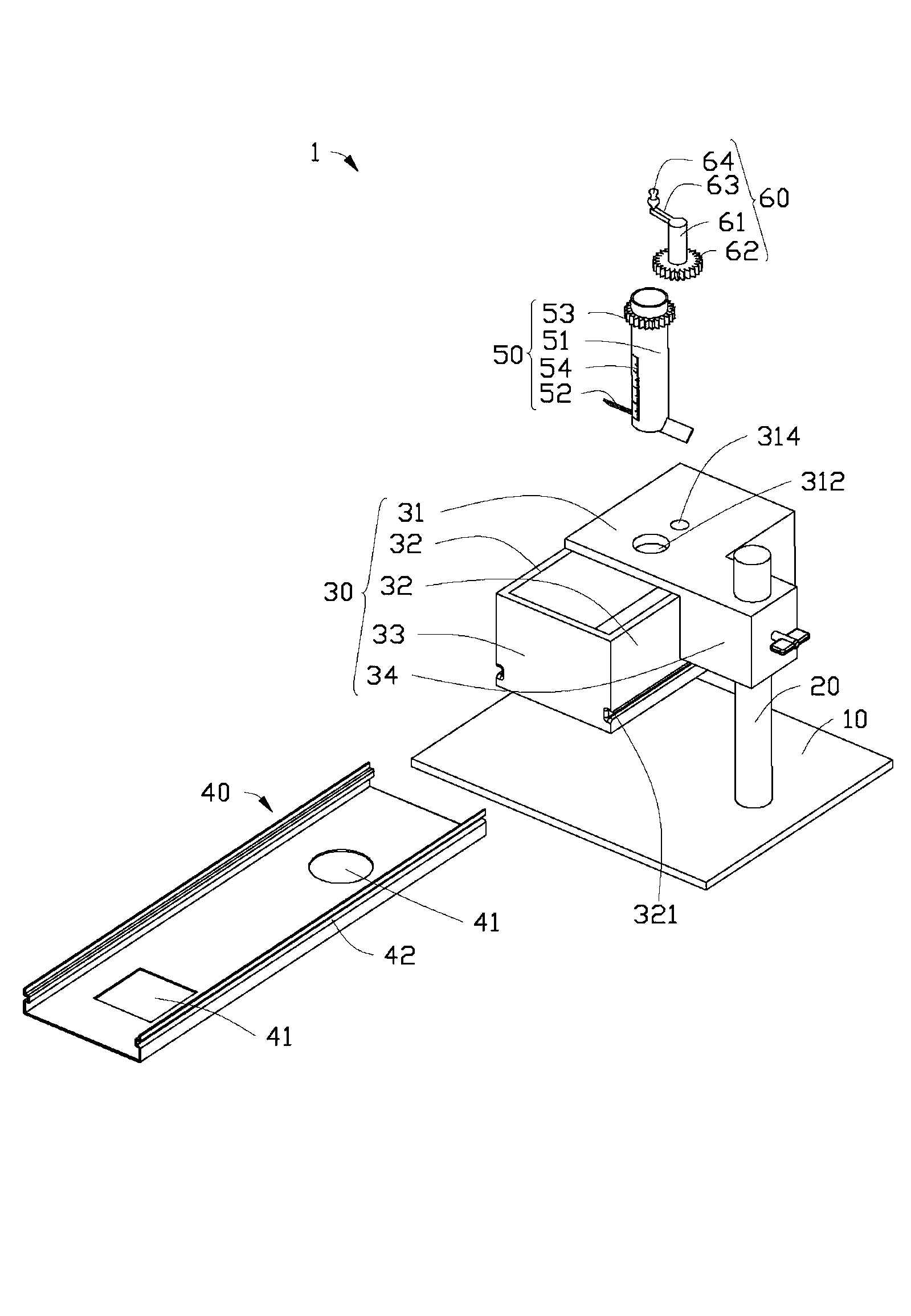
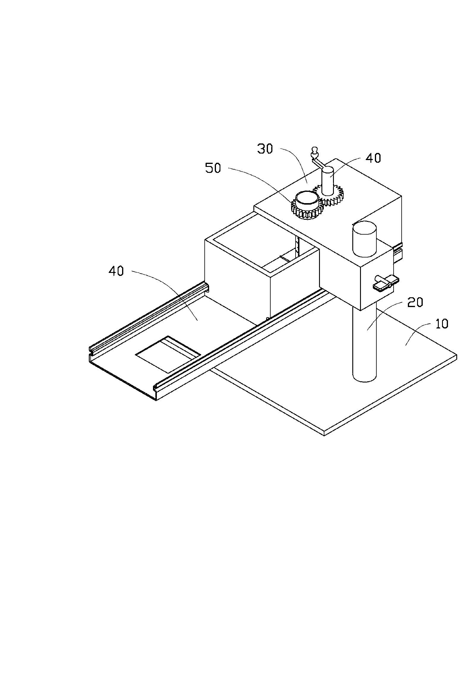
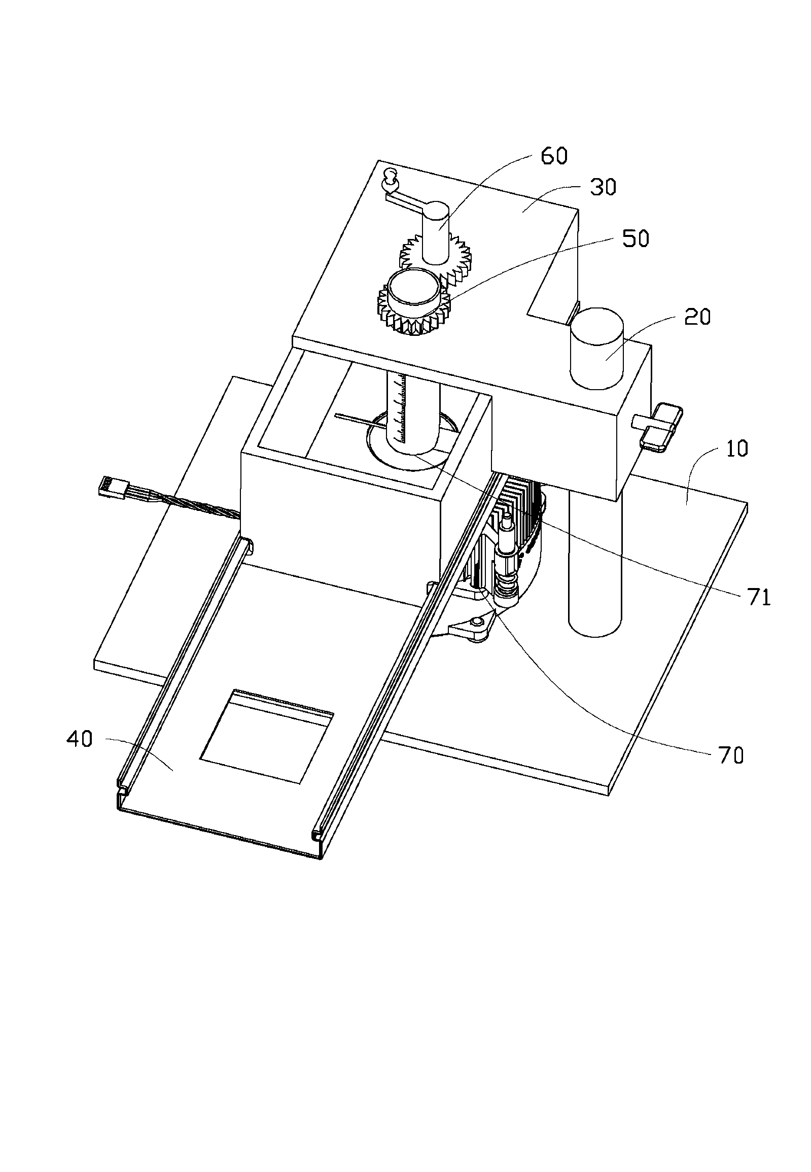
[0019] see figure 1 , in a preferred embodiment, a thermal paste applicator 1 includes a platform 10 for placing a radiator, a support column 20 arranged on the platform 10 , and a bracket fixed on the support column 20 30. A bottom plate 40 arranged at the bottom of the bracket 30 , a top plate 31 arranged at the top of the bracket 30 , a heat dissipation grease conduit 50 opened up and down and hollow, and a rotating handle 60 .

[0020] The platform 10 is used for placing the heat sink to be coated with thermal paste. The support column 20 is located on the side of the platform 10 close to the edge and is perpendicular to the platform 10 .

[0021] The bracket 30 includes two opposite side plates 32, two connecting plates 33 connecting the side plates 32, and the bracket 30 is fixed on the support column 20 so that the bracket 30 is relative to the support column 20 Lifting structure 34 that slides up and down. The side plate 32 , the connecting plate 33 and the top plate...


PUM


Abstract

A thermal paste smearing apparatus is used for smearing a thermal paste on the thermal contact surface of a radiator, and comprises a platform arranged on the radiator, a support column arranged on the platform, a support fixed on the support column, a baseboard arranged at the bottom of the support, a top board arranged at the top of the support, and a hollow thermal paste conduit having an upper opening and a lower opening, the baseboard is provided with a smearing hole, the top board is provided with a through hole, the thermal paste conduit penetrates through the through hole, the lower opening of thermal paste conduit aligns and is close to the smearing hole, and the lower opening of the thermal paste conduit is provided with smearing sheets. When the thermal paste is smeared, the radiator is disposed on the platform, the thermal contact surface of the radiator upward abuts against the smearing hole, the thermal paste is filled from the upper opening of the thermal paste conduit, the thermal paste conduit rotates around the central axis of the thermal paste conduit, and the smearing sheets rotate with the thermal paste conduit to uniformly smear the thermal paste on the thermal contact surface of the radiator.

Description

technical field [0001] The invention relates to a heat dissipation paste applicator. Background technique [0002] It is necessary to apply a layer of thermal paste between electronic components (such as CPU) and the heat sink to make the heat sink and the electronic components fully contact and improve the heat dissipation efficiency. In the traditional manual application method, due to the difficulty in controlling the amount and thickness of the heat dissipation paste, it is difficult to apply the heat dissipation paste evenly on the contact surface of the radiator and the electronic components, and the application efficiency and quality of the heat dissipation paste are relatively low. The quality of the coating will directly affect the working temperature of the electronic components, thereby affecting the performance and stability of the electronic components. In addition, in the mass assembly production of the factory, due to the difference of operators and their ope...

Claims


Application Information

Patent Timeline
Patent Type & Authority Applications(China)
IPC IPC(8): B05C5/02B05C11/04B05C11/10
CPCB05C5/00B05C11/02B05B12/20
Inventor 秦伟民李昌俊刘玉林
Owner NORTH CHINA UNIVERSITY OF SCIENCE AND TECHNOLOGY
Learn More