Adjustable wrench head of torque wrench

A technology of torque wrench and wrench head, which is applied to wrenches, screwdrivers, manufacturing tools, etc. It can solve the problems of low work efficiency and achieve the effects of high work efficiency, convenient and stable connection, and labor-saving rotation of the handwheel

Inactive Publication Date: 2013-06-26
ZHEJIANG HAOQING AUTOMOBILE MFG CO LTD +1
View PDF8 Cites 5 Cited by
  • Summary
  • Abstract
  • Description
  • Claims
  • Application Information

AI Technical Summary

Problems solved by technology

[0003] The purpose of the present invention is to overcome the disadvantages of the current torque wrench wrenches that need to be replaced with different specifications when the wrench heads are used for fasteners of different specifications, and the working efficiency is low, and to provide a torque wrench suitable for a variety of different specifications. Firmware, adjustable wrench head for torque wrench with high work efficiency

Method used


Image

  • Adjustable wrench head of torque wrench
  • Adjustable wrench head of torque wrench

Examples


Embodiment 1

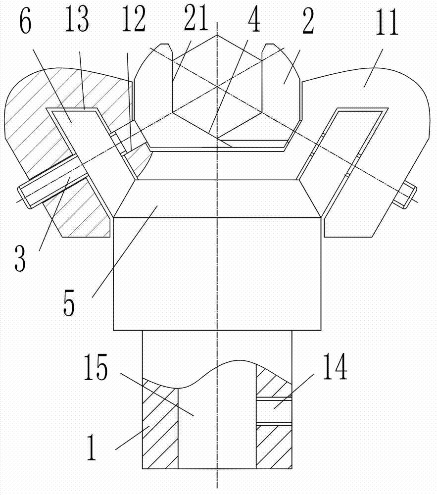
[0016] Embodiment 1, as attached figure 1 Shown: an adjustable wrench head of a torque wrench, including a connecting rod 1 with two symmetrical bumps 11 at one end, two wrenching rods located between the two bumps 11 and symmetrical to an axial section of the connecting rod 1 Claw 2 and two adjustment levers 3; two pull claws 2 opposite sides are respectively provided with a V-shaped notch 21; the angle between the two sides of the V-shaped notch 21 is 120 degrees; One side is respectively parallel to an axial section of the connecting rod 1; the other side of the two V-shaped notches 21 forms the closed end 4; each of the two protrusions 11 has a rod hole whose diameter matches the outer diameter of the adjusting rod 3 12. One end of each adjustment rod 3 passes through the rod hole 12 of a projection 11 and is fixedly connected to a pulling claw 2, and the angle bisector of the angle between the two sides of the V-shaped notch 21 and one of the adjustment rod 3 The shaft s...

Embodiment 2

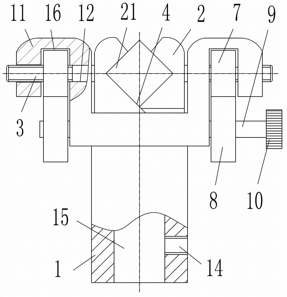
[0021] Embodiment 2, as attached figure 2 Shown: an adjustable wrench head of a torque wrench, including a connecting rod 1 with two symmetrical bumps 11 at one end, two wrenching rods located between the two bumps 11 and symmetrical to an axial section of the connecting rod 1 Claw 2 and two adjusting rods 3; two opposite sides of pulling claw 2 are respectively provided with a V-shaped notch 21; the angle between the two sides of V-shaped notch 21 is 90 degrees; both sides of V-shaped notch 21 The angle bisector of the included angle between the sides is perpendicular to the axis of the adjusting rod 3; the length of one side of the V-shaped notch 21 is less than the length of the other side; the other side of the two V-shaped notches 21 forms the closed end 4 ; Two projections 11 each have a rod hole 12 whose diameter is matched with the outer diameter of the adjustment rod 3; one end of each adjustment rod 3 passes through the rod hole 12 of a projection 11 and is fixedly ...


PUM


Abstract

The invention relates to the field of assembling tools, and aims to provide an adjustable wrench head of a torque wrench. The adjustable wrench head of the torque wrench comprises a connection rod, two wrench claws and two adjustment levers, wherein one end of the connection rod is symmetrically provided with two protruding blocks, and the two wrench claws and the two adjustment levers are between the two protruding blocks. V-shaped notches are formed in opposite sides of the two wrench claws. The inclined angle between two side edges of each V-shaped notche is 120 degrees. One side edges of the two V-shaped notches are parallel to a shaft section of the connection rod. The other side edges of the two V-shaped notches form a closed end. Rod holes are formed in the two protruding blocks. The diameters of the rod holes are matched with the outer diameters of the adjustment levers. One end of each adjustment lever penetrates through one rod hole of one protruding block and is fixedly connected with one wrench claw. The angle-bisecting of the inclined angle between the two side edges of the V-shaped notches is coincided with the shaft section of the connection rod. The adjustable wrench head of the torque wrench is provided with a drive mechanism used for driving the adjustment levers to do axial motion. The adjustable wrench head of the torque wrench is suitable for fastening pieces with different specifications, and is high in working efficiency.

Description

technical field [0001] The invention relates to the field of assembly tools, in particular to an adjustable wrench head of a torque wrench. Background technique [0002] A torque wrench is a commonly used tool for tightening fasteners such as bolts and nuts. The invention of Chinese patent notification number CN101653932A discloses a torque wrench, which includes an outer sleeve, a wrench head, and a torque adjustment component for adjusting the torque setting value of the wrench. The inner sleeve and the marking part that marks the fastener when the torque reaches the set value, and the inner main shaft, the limit connecting rod, the driving part and the elastic part are sequentially arranged in the outer sleeve from one end to the other end. The two ends of the main shaft are respectively connected with the wrench head and the limiting connecting rod, the other end of the limiting connecting rod is in contact with one end of the driving part, and the two ends of the elasti...

Claims


Application Information

Patent Timeline
Patent Type & Authority Applications(China)
IPC IPC(8): B25B13/10B25B13/58B25B23/00
Inventor 陈贵龙潘巨林
Owner ZHEJIANG HAOQING AUTOMOBILE MFG CO LTD
Why Eureka
Try Eureka