A self-breathing electrochemical oxygen generation system

A self-breathing, oxygen-generating system technology, applied in the electrolysis process, electrolysis components, cells, etc., can solve the problem of small flow of oxygen generators

Active Publication Date: 2016-08-31
江西德合医疗器械有限公司
View PDF7 Cites 3 Cited by
  • Summary
  • Abstract
  • Description
  • Claims
  • Application Information

AI Technical Summary

Problems solved by technology

[0003] The above oxygen generator only provides one oxygen flow path, and the flow rate of this oxygen generator is also relatively small

Method used


Image

  • A self-breathing electrochemical oxygen generation system
  • A self-breathing electrochemical oxygen generation system
  • A self-breathing electrochemical oxygen generation system

Examples


specific Embodiment 1

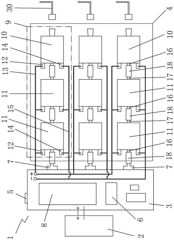
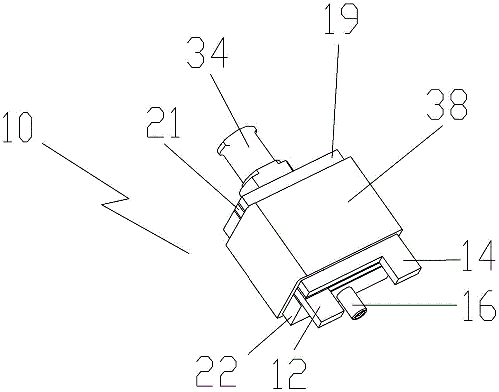
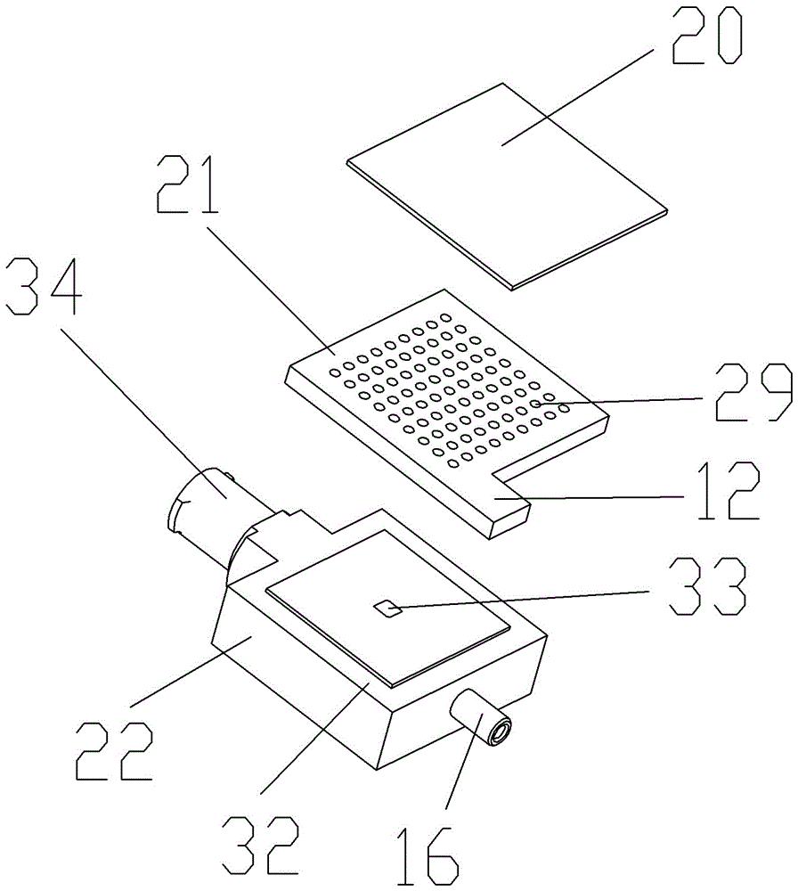
[0033] Specific embodiment one of the pure oxygen generating flow path 9: each pure oxygen generating flow path 9 includes a gas supply pure oxygen generating assembly 10, when the pure oxygen generating flow path 9 contains a pure oxygen generating assembly, the pure oxygen generating assembly The oxygen generation component is the gas supply pure oxygen generation component 10. At this time, the tail outlet pipe 16 of the gas supply pure oxygen generation component 10 is the inlet of the pure oxygen generation flow path 9, and the corresponding pressure input end of the pressure sensor 7 and the gas supply A sealing hose 18 is sheathed on the outer edge of the tail outlet pipe 16 of the pure oxygen generator assembly 10 , and the oxygen connector 34 of the pure oxygen generator assembly 10 is connected to the oxygen output pipe 30 .

specific Embodiment 2

[0034] The second specific embodiment of the pure oxygen generating flow path 9: when the pure oxygen generating flow path 9 contains two pure oxygen generating components, it includes a gas supply pure oxygen generating component 10 and an internal pure oxygen generating component 11. The tail outlet pipe 16 of the pure oxygen generation assembly 11 is the inlet of the pure oxygen generation flow path 9, the outer edge surface of the tail outlet pipe 16 of the gas supply pure oxygen generation assembly 10 and the front outlet pipe 17 of the internal pure oxygen generation assembly 11 A sealing hose 18 is set, the oxygen connector 34 of the air supply pure oxygen generating assembly 10 is connected to the oxygen output pipe 30, and the outer edge surface of the tail outlet pipe 16 of the internal pure oxygen generating assembly 11 and the pressure input end of the pressure sensor 7 is covered with a sealing soft tube. Tube 18.

specific Embodiment 3

[0035] Specific embodiment three of the pure oxygen generating flow path 9: when the pure oxygen generating flow path 9 contains at least three pure oxygen generating components, it includes a gas supply pure oxygen generating component 10, and the rest are internal pure oxygen generating components 11, At this time, the tail outlet pipe 16 of the internal pure oxygen generation assembly 11 adjacent to the pressure sensor 7 is the inlet of the pure oxygen generation flow path 9, and the oxygen connector 34 of the gas supply pure oxygen generation assembly 10 is connected to the oxygen output pipe 30. Oxygen generating components 11 are sequentially arranged on the side close to the control system 3, and the internal pure oxygen generating component 11 located at the farthest end of the control system 3 is connected to the gas supply pure oxygen generating component 10, and the tail of the gas supply pure oxygen generating component 10 is drawn out Pipe 16 and the outer edge sur...


PUM


Abstract

The invention provides a self-breathing electrochemical oxygen generation system which has a plurality of oxygen flow paths simultaneously and can increase the oxygen flow of each flow path as required to meet the requirement of oxygen in actual use. The self-breathing electrochemical oxygen generation system comprises pure oxygen generation assemblies and is characterized by further comprising a power supply system, a control system and at least one pure oxygen generation flow path, wherein each pure oxygen generation flow path is internally provided with at least one pure oxygen generation assembly, the pure oxygen generation flow paths are combined and arranged to form a pure oxygen generation assembly array, the control system is externally connected with the power supply system and is internally provided with a power supply switch, a temperature and humidity sensor, pressure sensors and a display screen, the number of the pressure sensors is same as the number of the pure oxygen generation flow paths in the pure oxygen generation assembly array, and the pressure sensors are connected with inlets of corresponding pure oxygen generation flow paths.

Description

technical field [0001] The invention relates to the technical field of electrochemical production of pure oxygen, in particular to a self-breathing electrochemical oxygen production system. Background technique [0002] Existing self-breathing electrochemical oxygen concentrator, its patent publication number: CN102851681A, application date: April 1, 2012 The patent record is as follows: the present invention provides self-breathing electrochemical oxygen concentrator, which makes the external After the oxygen output pipe is blocked, the pressure inside the pure oxygen generating component is ensured to be in the normal range through manual and timely operation, so as to ensure the normal operation of the pure oxygen generating component and thus ensure the long service life of the oxygen generator. It includes an outer shell, and the outer shell includes an upper shell and a lower shell. It is characterized in that: the cavity formed by the upper shell includes a battery in...

Claims


Application Information

Patent Timeline
Patent Type & Authority Patents(China)
IPC IPC(8): C25B1/02C25B9/00C25B15/00
Inventor 胡鸣若小笠原亮曹广益
Owner 江西德合医疗器械有限公司
Why Eureka
Try Eureka