Self-powered deposit box

A storage box and self-powered technology, which is applied to safes, collectors, electric vehicles, etc., can solve the problems of potential safety hazards, external power supply of storage boxes, etc., and achieve the effects of protecting the environment, eliminating potential safety hazards, and exempting electricity bills

Inactive Publication Date: 2013-06-26
苏海洋
6 Cites 1 Cited by

AI-Extracted Technical Summary

Problems solved by technology

[0002] Storage boxes have been widely used in bathhouses, supermarkets and other places, but because ordinary storage boxes require external power supply, it is required to have an external power supply around the installation site, which puts forward cost requirements for the installation, construction, and maintenance of storage boxes. pose a s...

Abstract

The invention provides a self-powered deposit box, belongs to the field of generator application, in particular to the filed where a generator supplies power to a terminal. The self-powered deposit box solves the technical problem that a deposit box depends on an external power source and enables the deposit box not to depend on the external power source any more, and therefore a base is provided for wide distribution of the deposit box. According to the self-powered deposit box, a manual generator and an energy storage battery are used as main power sources for work of the deposit box, and therefore use of the external power source can be avoided, and the problem of depending on the external power can be solved. As is known to all, the deposit box can solve the congregation problem that one person puts objects while the other person takes the objects in the logistics process and reduces going-out frequency of people in city life, then the use of deposit box for object delivery is a component for environment protection and low-carbon life, and if the deposit boxes can be arranged widely, energy conservation and emission reduction in the city life can be promoted. According to the self-powered deposit box, in the process of manual electricity generation, people supply energy to the generator in a body-building method, the electricity process promotes green-living ideas of exercise and body building and healthy life.

Application Domain

Batteries circuit arrangementsElectric power +2

Technology Topic

Supply energyElectricity +6

Image

  • Self-powered deposit box
  • Self-powered deposit box
  • Self-powered deposit box

Examples

  • Experimental program(1)

Example Embodiment

[0027] The technical solutions in the embodiments of the present invention will be clearly described below in conjunction with the drawings in the embodiments of the present invention. It should be noted that this embodiment is only an embodiment of the present invention, but not all embodiments.
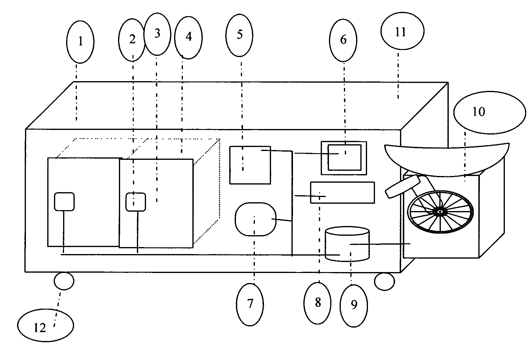
[0028] Please refer to figure 1 , which shows a schematic circuit connection diagram of a self-powered storage box of the present invention. It can be seen from the schematic diagram that the user can sit or lie on the upper surface 11 of the storage box, and turn the legs to turn the pedal generator 10 to directly supply power to the battery power supply module 9, and then the battery power supply module 9 transmits power to the storage space door Lock 2, authentication module 5, display module 6, central computing unit 7, user input module 8, so that the whole system obtains electric energy.
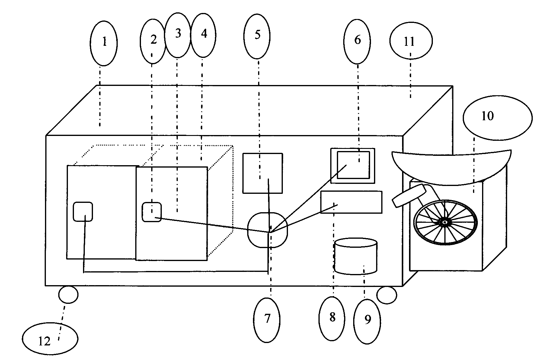
[0029] Please refer to figure 2 , which shows a schematic diagram of data connection of a self-powered storage box of the present invention. It can be seen from the schematic diagram that the central computing unit is the computing core of the system, which determines the behavior and actions of the storage space door lock 2, authentication module 5, display module 6, and user input module 8.
[0030] figure 1 and figure 2 Medium locker wheels enable wider and more flexible distribution of lockers.
[0031] Please refer to image 3 , which shows a working flow chart of a self-powered locker of the present invention in the process of depositing items by the user. Since the cooperation between the storage space door lock 2, the authentication module 5, the display module 6, the central computing unit 7, and the user input module 8 belongs to a known technology, it will not be repeated here, and only the process of "depositing items" in the flow chart is used. logo.
[0032] The work flow chart can be described as: the customer intends to deposit items, first comes to the front of the locker box body 1, if the display module 6 finds that the system is in a shutdown state, then he needs to sit or lie on the upper surface 11 of the locker box body, Utilize the pedal generator 10 to charge the battery power supply module 9, when the battery reaches a certain amount of power, the battery power supply module 9 starts the system, and the user uses the storage space door lock 2, the authentication module 5, the display module 6, the central computing unit 7, User input module 8 deposits items, then exits.
[0033] Please refer to Figure 4 , which shows the working flow chart of the self-powered locker of the present invention in the process of taking out items by the user. Because the cooperation between the storage space door lock 2, the authentication module 5, the display module 6, the central computing unit 7, and the user input module 8 belongs to the known technology, so it will not be described here, and only the process of "removing items" in the flow chart is used to identify .
[0034] The work flow chart can be described as: the customer intends to take out the articles, first comes to the front of the locker 1, if the display module 6 finds that the system is in a shutdown state, then he needs to sit or lie on the upper surface 11 of the locker box, use the foot pedal The electric generator 10 charges the battery power supply module 9. When the battery reaches a certain amount of power, the battery power supply module 9 starts the system, and the user uses the object space door lock 2, the authentication module 5, the display module 6, the central computing unit 7, and the user input module 8 Take out the item, and leave.
[0035] It should be noted that the above two processes are the worst case, and the user needs to generate electricity before each use. In fact, in most cases, when people are sitting or lying on the upper surface 11 of the storage box to rest , the pedal generator 10 can be easily and happily pushed to charge the battery power supply module 9 . Or with the assistance of solar generators or wind generators, users do not need to perform power generation operations every time.

PUM

no PUM

Description & Claims & Application Information

We can also present the details of the Description, Claims and Application information to help users get a comprehensive understanding of the technical details of the patent, such as background art, summary of invention, brief description of drawings, description of embodiments, and other original content. On the other hand, users can also determine the specific scope of protection of the technology through the list of claims; as well as understand the changes in the life cycle of the technology with the presentation of the patent timeline. Login to view more.

Similar technology patents

Sliding door arrangement

PendingCN111749582AReduce electrical wiringReduce installation costs
Owner:DORMAKABA DEUT GMBH

Matrix type flexible switching charging stack

PendingCN109878358AReduced Chance of InjuryReduce installation costs
Owner:泸州能源投资有限公司

Single-hole type heat exchanger

PendingCN111121211AHigh installation efficiencyReduce installation costs
Owner:广州市亿加环境科技有限公司

Classification and recommendation of technical efficacy words

  • Reduce installation costs
  • Free electricity

Retractable castor mechanism of rack

Owner:深圳市阿尔法特网络环境有限公司

Multi-path single-phase and three-phase mixed electric energy metering device and method

InactiveCN103728493AHigh integration and flexibilityReduce installation costs
Owner:SUZHOU IND PRAK NEW HONGBO COMM TECH

Floor board edge sealing strip

Owner:ZHEJIANG MEIDIAN NEW MATERIAL

Seeding cover employing solar energy

InactiveCN104170689AFree electricitySimple structure
Owner:HINOX SHOJI
Why Eureka
Try Eureka