An automatic anchoring and card releasing device for a cable-transmitted flame cutting device

A technology of flame cutting and cable transmission, used in wellbore/well components, earth-moving drilling and other directions to ensure safety

Active Publication Date: 2015-10-07
NORTH SCHLUMBERGER OILFIELD TECH XIAN
View PDF6 Cites 2 Cited by
  • Summary
  • Abstract
  • Description
  • Claims
  • Application Information

AI Technical Summary

Problems solved by technology

In the prior art, there is no anchor release device for the flame cutting device with cable transmission. When working, the weight of the well fluid mainly presses the cutter to prevent it from moving, but this method can only be used in a well fluid environment with a certain depth. use, with great limitations

Method used


Image

  • An automatic anchoring and card releasing device for a cable-transmitted flame cutting device
  • An automatic anchoring and card releasing device for a cable-transmitted flame cutting device
  • An automatic anchoring and card releasing device for a cable-transmitted flame cutting device

Examples


Embodiment 1

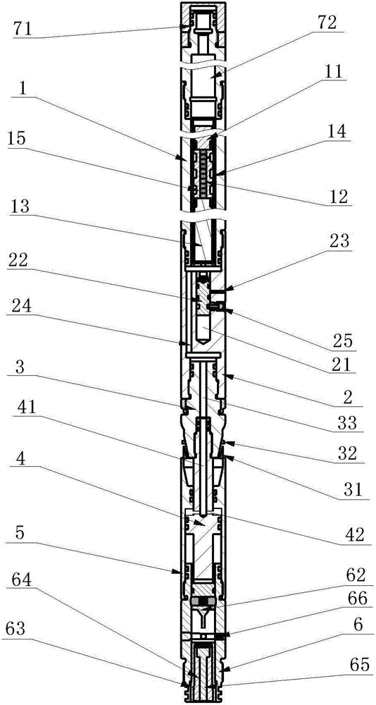
[0037] refer to Figure 1 to Figure 4 The automatic anchoring and jam-releasing device of the cable-transmitted flame cutting device provided in this embodiment is to anchor the flame cutting device: "annular combustion cutter" on the inner wall of the target pipe string during the cutting process, and the device automatically Release the jam, and lift the cutter out to cut the pipe string under the lifting force of the cable.

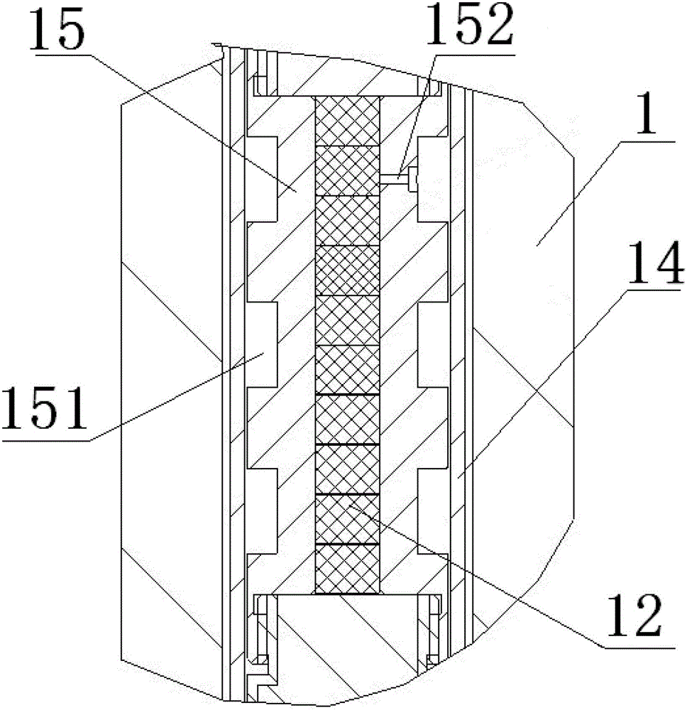
[0038]The device specifically includes a cylindrical charge combustion chamber 1, the upper end of which is connected to an ignition device, the combustion chamber 1 is equipped with a primary primary charge 11, a secondary primary charge 13 and a delay charge 12, and the delay The drug 12 is installed between the first-level main charge 11 and the second-level main charge 13, and the first-level main charge 11, the delay charge 12 and the second-level main charge 13 are loaded into the open injection shell 14 and then installed into the combustion ch...

Embodiment 2

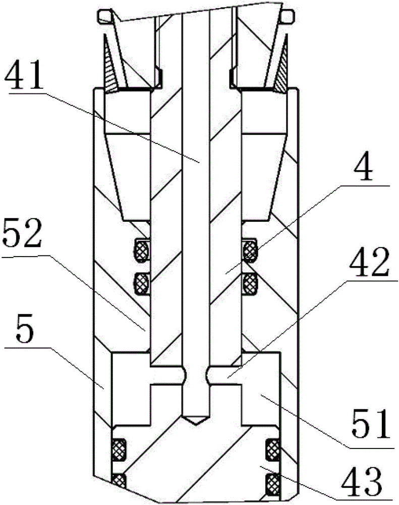
[0047] The difference between this embodiment and Embodiment 1 is that the shear ring 32 is not set on the slider joint 3, but three pins are inserted in the circumferential direction between the piston rod 4 and the support cylinder 5, and the number of pins installed is It can be determined according to the downhole pressure, generally 2 to 6.

Embodiment 3

[0049] refer to Figure 1 to Figure 4 In this embodiment, on the basis of Embodiment 1, a safety device 66 is provided between the firing pin 62 and the ignition device. The safety device 66 includes a piston hole radially opened in the lower joint 6, and one end of the piston hole is Sealed end, the other end is the open end that communicates with the outside world, a spring 663 and a piston 661 are sequentially assembled in the piston hole from the sealed end to the open end, and an axial through hole 662 is opened on the piston 661, and the axial through hole 662 deviates from the end of the firing pin 62 in the radial direction, which can prevent the firing pin 62 from hitting the propellant 65 by mistake during transportation and installation. When the device is working in the downhole, the piston 661 moves towards the sealing end of the piston hole under the pressure of the liquid in the well. Movement, and then make the axial through hole 662 and the firing pin 62 face ...


PUM


Abstract

The invention discloses an automatically anchoring unfreezing device for a flame cutting device of cable transmission so that anchoring, ignition and unfreezing of a down-hole working device are effectively and continuously achieved. The automatically anchoring unfreezing device for the flame cutting device of the cable transmission comprises first-level main load powder, delay load powder, second-level main load powder, a pressure release hole which is stopped by a pressure release piston, a sliding block, a piston rod, a support cylinder which is sleeved outside the piston rod and a bump sparking device which is connected with the lower end of the support cylinder. The support cylinder is pushed by gas produced by burning of the first-level main load powder to move upward, then the sliding block is pushed by the support cylinder to move upward to be clamped on a construction pipe wall, and the anchoring of the device is achieved, meanwhile, the bump sparking device is driven by the support cylinder to move upward and sparks after being bumped by the piston rod, at the moment, the delay powder starts to burn, pressure in the device keeps unchanged, the ignition of the bump sparking device to the flame cutting device is completed, then the second-level main load powder starts to burn, the pressure in the device rises, outleakage happens in the pressure release hole stopped by the pressure release piston, the gas is released out of the pressure release hole, the pressure in the device falls and the unfreezing of the device is achieved after the sliding block falls back.

Description

technical field [0001] The invention relates to an automatic anchoring and clamping release device for a flame cutting device transmitted by a cable, which is specifically used for anchoring and automatically releasing the clamping of the construction device during the cable transmission in the oil and gas well construction process. Background technique [0002] In oil field exploitation, cables are often used to transmit oil well blasting and cutting devices such as fracturing bullets, perforating guns and cutters to the blasting and cutting position. Anchor the device, and automatically release the anchor after the work is completed, and lift the blasting cutting device out of the well in time. [0003] For example, in the development process of oil and gas wells at home and abroad, the problem of pipe sticking is often encountered. Generally, the main method to deal with pipe stuck accidents is to cut the stuck pipe. Cutting method, these two cutting methods use cables t...

Claims


Application Information

Patent Timeline
Patent Type & Authority Patents(China)
IPC IPC(8): E21B23/04
Inventor 高强张炳军周扬李森元路利军慕光华袁铁刚孙志忠贺红民钮元元
Owner NORTH SCHLUMBERGER OILFIELD TECH XIAN
Why Eureka
Try Eureka