Two-position double-control combined valve for hydraulic device

A technology of hydraulic equipment and combined valve, applied in the field of hydraulic control valve, can solve the problems of high maintenance cost, unreasonable design, waste of physical strength, etc., and achieve the effects of safe and reliable operation, simple and reasonable structure, and lightening of workload.

Active Publication Date: 2013-06-26
CHINA MCC17 GRP
View PDF7 Cites 5 Cited by
  • Summary
  • Abstract
  • Description
  • Claims
  • Application Information

AI Technical Summary

Problems solved by technology

[0002] The design of control valves used in existing hydraulic machinery is not standardized, neither common nor reasonable, and mainly has the following disadvantages: 1. Large volume and waste of energy and materials; 2. Inconvenient installation; 3. High maintenance costs; 4. 1. The operation is difficult and the speed cannot be accurately controlled, especially for novice operators who are either too fast or too slow and accidents often occur; 5. The safety performance is poor and the pressure cannot be relieved at the operating position; 6. It is difficult to purchase. Most of the existing equipment can not be bought for one car and one sample, and the cost increases and wastes seriously due to delays in work and time. 7. Failure to decompress in time causes the mechanical transmission system to wear out and waste a lot of fuel; 8. Equipment The utilization rate is low, and a piece of equipment can only do one kind of work at a time

Method used


Image

  • Two-position double-control combined valve for hydraulic device
  • Two-position double-control combined valve for hydraulic device
  • Two-position double-control combined valve for hydraulic device

Examples


Embodiment Construction

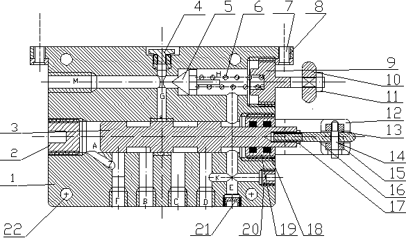
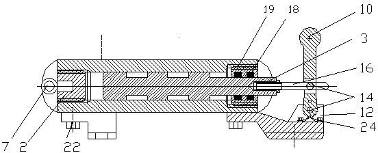
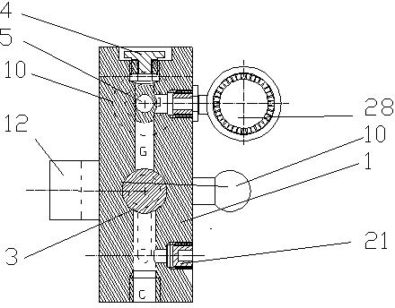
[0020]A two-position double-control combination valve for hydraulic equipment provided by the present invention includes a plate 1; On one plane, each oil circuit channel that is used to communicate with each other is processed, and the main through hole A for the main oil circuit control valve is provided in the horizontal direction from left to right at the intersection of the horizontal plane weakly below the upper and lower centers of the plate 1. The inner hexagonal plug 2 is processed on the left surface of the main through hole A, and the inner hexagonal plug 2 is screwed from left to right on the inner hexagonal plug. The left end surface of the inner hexagonal plug 2 is not Stretch out the left plane of the plate fast 1, near the right end of the inner hexagon plug 2, there is a second through hole Z for decompression obliquely down to the right and used to communicate with the first through hole F; The top of the main through hole A is provided with a third through h...


PUM


Abstract

The invention provides a two-position double-control combined valve for a hydraulic device, and belongs to the technical field of hydraulic control valves. The main structure of the combined valve is a whole processed by a tetragonal thick cast steel material, oil-way channels which are communicated with each other are processed in a plane of the middle portion of the front part and the rear part of the whole plate, a smooth main through hole for a main oil-way control valve is formed in the connection position of a horizontal plane in the horizontal direction from left to right, wherein the connection position of the horizontal plane is slightly lower than the vertical center. Through holes for various uses are formed in the central plane of the main through hole and are communicated with each other, a pressure gage is installed above a plane body communicated with the through holes, two control rods for operating and rotary pressure adjusting valves are installed on the right side of a main body, wherein the rotary pressure adjusting valves have multiple control functions. The combined valve has the advantages of being simple in structure, convenient to install, simple, safe and reliable in operation, low in manufacturing cost, good in generality, low in oil consumption and the like, and can improve working efficiency and working range of the hydraulic device.

Description

technical field [0001] The invention belongs to the technical field of hydraulic control valves, in particular to a two-position double-control combination valve used in hydraulic equipment. technical background [0002] The design of control valves used in existing hydraulic machinery is not standardized, neither common nor reasonable, and mainly has the following disadvantages: 1. Large volume and waste of energy and materials; 2. Inconvenient installation; 3. High maintenance costs; 4. 1. The operation is difficult and the speed cannot be accurately controlled, especially for novice operators who are either too fast or too slow and accidents often occur; 5. The safety performance is poor and the pressure cannot be relieved at the operating position; 6. It is difficult to purchase. Most of the existing equipment can not be bought for one car and one sample, and the cost increases and wastes seriously due to delays in work and time. 7. Failure to decompress in time causes t...

Claims


Application Information

Patent Timeline
Patent Type & Authority Applications(China)
IPC IPC(8): F15B13/02
Inventor 许翊像
Owner CHINA MCC17 GRP
Why Eureka
Try Eureka