Weighing cell operating on the principle of electromagnetic force compensation with optoelectronic position sensor

A weighing cell, compensation principle technology, applied in the field of balances

Active Publication Date: 2013-06-26
METTLER TOLEDO INC
View PDF7 Cites 13 Cited by
  • Summary
  • Abstract
  • Description
  • Claims
  • Application Information

AI Technical Summary

Problems solved by technology

Hysteresis and aging phenomena can be caused by slight misalignment of the connection areas between weighing cell components with different thermal expansions

Method used


Image

  • Weighing cell operating on the principle of electromagnetic force compensation with optoelectronic position sensor
  • Weighing cell operating on the principle of electromagnetic force compensation with optoelectronic position sensor
  • Weighing cell operating on the principle of electromagnetic force compensation with optoelectronic position sensor

Examples


Embodiment Construction

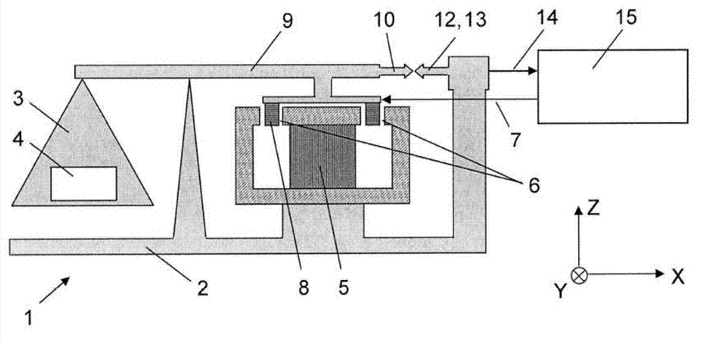
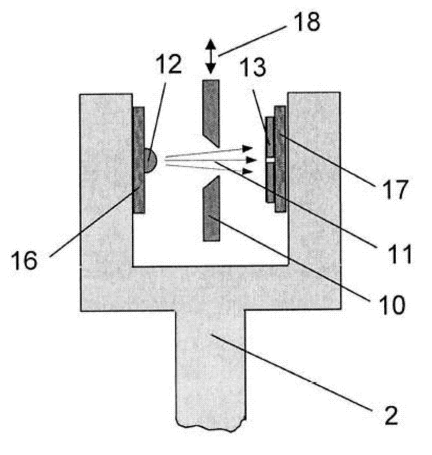
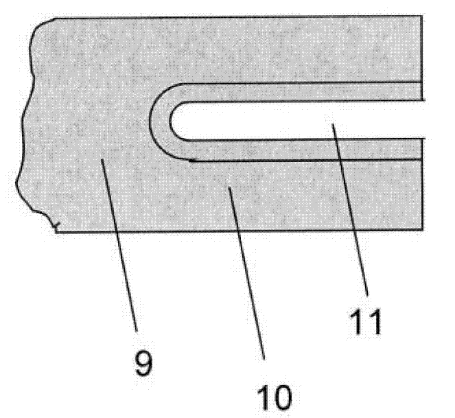
[0041] figure 1 It schematically shows a weighing unit with electromagnetic force compensation and photoelectric position sensor. Add a Cartesian coordinate system X, Y, Z as a reference, where X axis and Z axis are located figure 1 In the drawing plane, and the Y axis points to the space behind the drawing plane. The identifiable elements of the weighing unit 1 in the figure include a fixed base part 2; a load receiver 3, which is constrained by a balance beam 9 to be guided and movable relative to the base part 2; firmly installed on the base part 2 The cup-shaped permanent magnet system 5 (shown in cross-sectional view) of the permanent magnet system; the air gap 6 of the permanent magnet system, the coil 8 conducting the compensation current 7 is movably suspended in the air gap; and the load receiver 3 and the coil 8 The force-transmitting mechanical connection between the two is in the form of a balance beam 9 here. Photoelectric position sensor ( figure 1 Is displayed s...


PUM


Abstract

A weighing cell based on the principle of electromagnetic force compensation. A permanent magnet system is mounted on a base part and includes an air gap within which is suspended a coil that is connected to a load receiver through a force-transmitting mechanism. The coil carries an electrical compensation current when the weighing cell is in operation. An optoelectronic position sensor is also included, and its signal corresponds to the deflection of the coil from a zero position which occurs as a result of placing a load on the load receiver. A closed-loop controller regulates the compensation current in response to the sensor signal in such a way that the coil and the load receiver that is connected to it are returned to their zero position by the electromagnetic force that is acting between the coil and the permanent magnet.

Description

Technical field [0001] The invention relates to a balance with a photoelectric position sensor based on the principle of electromagnetic force compensation, especially a weighing unit. Background technique [0002] The principle of electromagnetic force compensation has wide applications in different types of balances used in commerce, industry and laboratories. This principle is particularly strong in that it allows balances with high measurement accuracy to be realized. For example, it is possible to measure a weighing load of 100 grams with a measurement resolution of 0.01 mg through an analytical balance operating on the principle of electromagnetic force compensation, that is, the accuracy is one part in ten million. [0003] The type of balance or weighing unit to which the present invention belongs has a fixed base part and a load receiver constrained to the base part so as to allow the load receiver to be guided relative to the base part, wherein the load receiver is used ...

Claims


Application Information

Patent Timeline
Patent Type & Authority Applications(China)
IPC IPC(8): G01G19/00
CPCG01G7/04G01G23/48
Inventor A·梅茨格S·巴尔蒂斯伯格H-R·布克哈德C·贝甘M·于斯泰尔
Owner METTLER TOLEDO INC
Why Eureka
Try Eureka