
Electric cable surface optical fiber temperature measuring tape

A technology of optical fiber temperature measuring belt and cable, which is applied in the optical field, can solve the problems of chronic aging of insulation layer, fire, property loss, etc., achieve accurate and true data, and solve the effect of waterproof and dustproof

Inactive Publication Date: 2013-06-26
东捷光电科技(苏州)有限公司
View PDF9 Cites 0 Cited by
  • Summary
  • Abstract
  • Description
  • Claims
  • Application Information

AI Technical Summary

Problems solved by technology

[0002] The working temperature of the power cable in the power grid is a very important operating parameter of the power system. This parameter is directly related to whether the system can operate safely and reliably for a long time. Generally speaking, to ensure the normal operation of the power cable, it is necessary to control the temperature of the surface of the cable core not to exceed The withstand temperature of the cable insulation layer; otherwise, it will cause chronic aging of the insulation layer, causing fire or even explosion over time, and even causing a fire in a short period of time, resulting in line burnout and large-scale power outages, resulting in major property losses; for For newly-made cables, the temperature-measuring optical fiber can be embedded in the cable to measure the conductor temperature of the cable; for the old cables in use, the temperature-measuring optical fiber is generally laid in parallel with the cable to measure the surface temperature of the cable; but Since the temperature measuring optical fiber laid in parallel is directly in contact with the external environment, it will be affected by the temperature of the external environment, resulting in the temperature monitored by the temperature measuring optical fiber is not the real temperature of the cable, which will eventually affect the monitoring data measurement of the cable current carrying capacity

Method used


Image

  • Electric cable surface optical fiber temperature measuring tape

Examples


Embodiment Construction

[0012] The present invention is described below in conjunction with accompanying drawing.

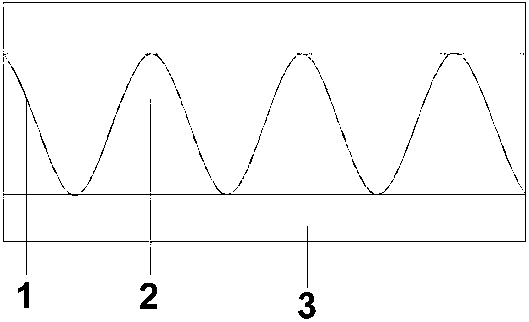
[0013] as attached figure 1 As shown, a cable surface optical fiber temperature measuring belt according to the present invention includes a temperature measuring optical fiber 1, a waterproof glue 2 and an insulating belt 3; the waterproof glue 2 is a viscous and waterproof silica gel; the waterproof glue 2 is arranged on the lower surface of the insulating belt 3; the temperature measuring optical fiber 1 is distributed on the lower side of the insulating belt 3 in a sine wave through the waterproof glue 2.

[0014] When installing, just paste the side of the thermal insulation belt 3 on which the temperature measuring optical fiber 1 and the waterproof glue 2 are attached to the surface of the cable under test.

[0015] Due to the application of the above-mentioned technical solution, the present invention has the following advantages compared with the prior art:

[0016] In the ca...


PUM


Abstract

The invention discloses an electric cable surface optical fiber temperature measuring tape which comprises a temperature-measuring optical fiber, waterproof glue and a heat-insulating tape. The waterproof glue is adhesive and waterproof and is arranged on the lower surface of the heat-insulating tape, and the temperature-measuring optical fiber is arranged on the lower side of the heat-insulating tape. The temperature-measuring optical fiber and the outside environment are parted by the heat-insulating tape with a function of heat insulating, so that the internal temperature-measuring optical fiber directly contacts with the surface of an electric cable and is free of influences by temperature of the outside environment, and obtained measurement data are more accurate and truer; and the temperature-measuring optical fiber and the heat-insulating tape are closely bonded by using the waterproof glue, so that the temperature-measuring optical fiber is isolated from the outside environment and is free of influences of rain water and dust, and the problem of water proofing and dust proofing of the temperature-measuring optical fiber is solved.

Description

technical field [0001] The invention relates to an optical fiber temperature measuring belt, in particular to an optical fiber temperature measuring belt on the surface of a cable which is convenient for measuring the surface temperature of a cable, and belongs to the field of optical technology. Background technique [0002] The working temperature of the power cable in the power grid is a very important operating parameter of the power system. This parameter is directly related to whether the system can operate safely and reliably for a long time. Generally speaking, to ensure the normal operation of the power cable, it is necessary to control the temperature of the surface of the cable core not to exceed The withstand temperature of the cable insulation layer; otherwise, it will cause chronic aging of the insulation layer, causing fire or even explosion over time, and even causing a fire in a short period of time, resulting in line burnout and large-scale power outages, re...

Claims


Application Information

Patent Timeline
Patent Type & Authority Applications(China)
IPC IPC(8): G01K11/32
Inventor 吕政鸿
Owner 东捷光电科技(苏州)有限公司
Learn More