
Electro-hydraulic loading device for reducer test

A technology of loading device and reducer, which is applied in the test of machine gear/transmission mechanism, fluid pressure actuating device, servo motor, etc., can solve the problem of inability to obtain technical parameters of high-efficiency reducer, poor stability of loading performance, and large size of magnetic powder brake and other problems, to achieve the effect of stable loading performance, stable performance and large loading torque

Inactive Publication Date: 2013-06-26
WENZHOU UNIVERSITY
View PDF5 Cites 15 Cited by
  • Summary
  • Abstract
  • Description
  • Claims
  • Application Information

AI Technical Summary

Problems solved by technology

For the performance test of this kind of brake reducer, it is necessary to carry out the loading test under the rated torque. At present, the common test method is: use the magnetic powder brake to realize the loading, the structure is simple, and the control is convenient. Large, severe heat generation, and poor loading performance stability
A box-shaped sealed power flow reducer test device has also been proposed, which can effectively test the relevant technical parameters of high-torque and large-speed-ratio reducers. The technical parameters of the high-efficiency reducer are less convenient to use

Method used


Image

  • Electro-hydraulic loading device for reducer test
  • Electro-hydraulic loading device for reducer test
  • Electro-hydraulic loading device for reducer test

Examples


Embodiment Construction

[0017] The present invention will be further described below in conjunction with the accompanying drawings and embodiments, but not as a basis for limiting the present invention.

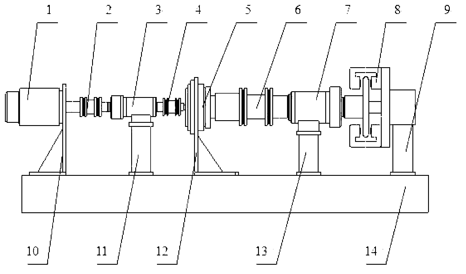
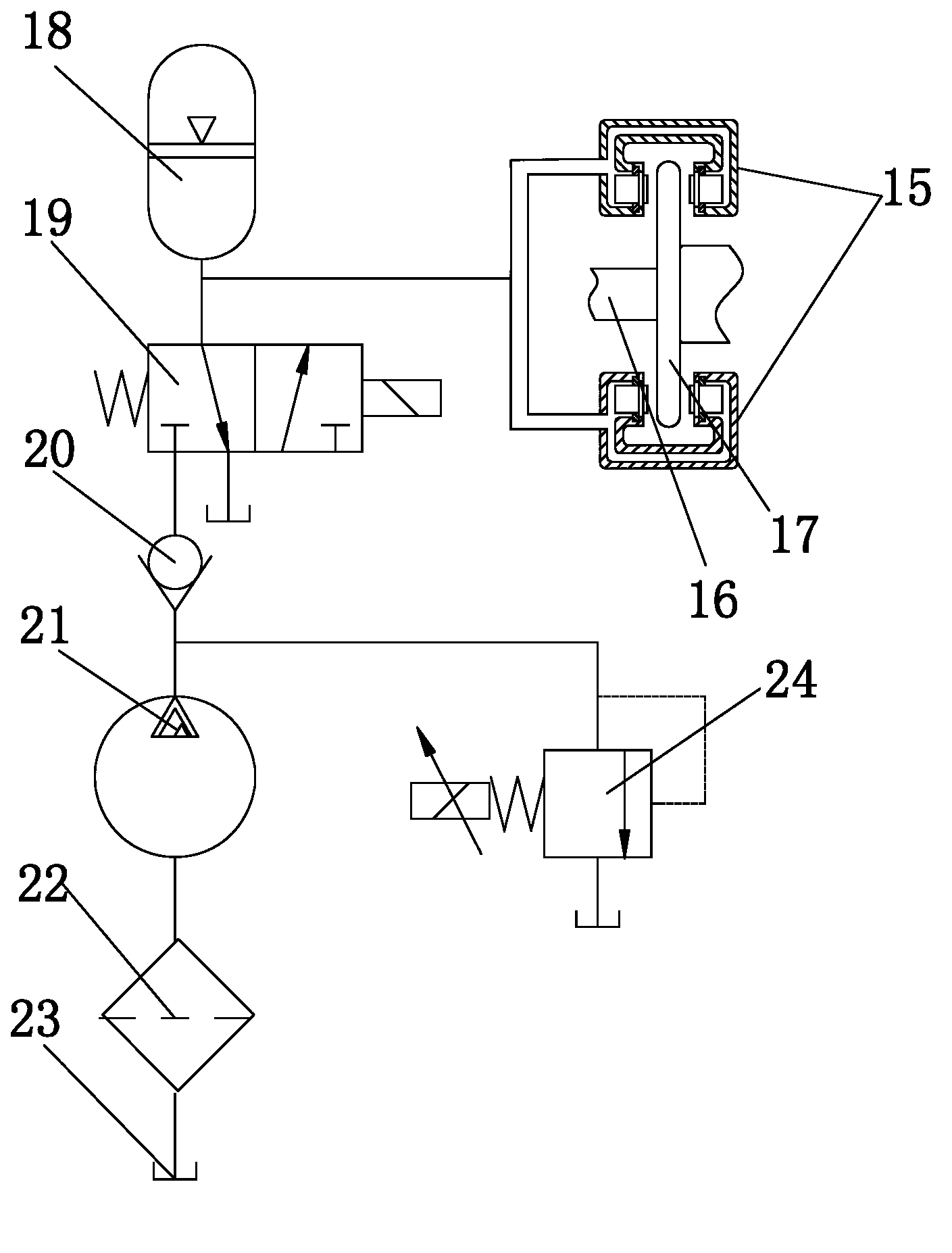
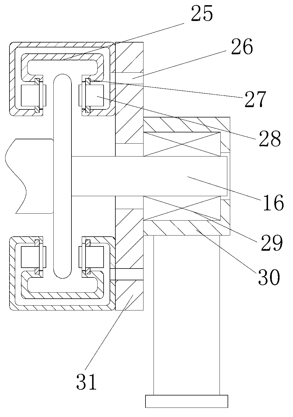
[0018] Example. An electro-hydraulic loading device for speed reducer testing, constituted as Figure 1-4 As shown, the base 14 is included, and the base 14 is provided with a drive motor 1, a first coupling 2, a torque angular displacement sensor 3 at the input end of the reducer, a second coupling 4, and a drive motor 1, which is kept horizontally coaxial and connected in sequence. Reducer 5, third coupling 6, torque angular displacement sensor 7 at the output end of the reducer, and electro-hydraulic loading mechanism 8. The electro-hydraulic loading mechanism 8 includes a loading cylinder 15, and a rotating shaft with a brake disc 17 is arranged in the loading cylinder 15 16. The loading cylinder 15 is sequentially connected with an accumulator 18 , a switching valve 19 , a check valve 20 , a h...


PUM


Abstract

The invention discloses an electro-hydraulic loading device for a reducer test. The electro-hydraulic loading device comprises a base (14). A driving motor (1), a first coupler (2), a torque angle displacement sensor (3) of a reducer input end, a second coupler (4), the to-be-tested reducer (5), a third coupler (6), a torque angle displacement sensor (7) of a reducer output end and an electro-hydraulic loading mechanism (8) are kept horizontally coaxial and connected in sequence are arranged on the base (14). The electro-hydraulic loading mechanism (8) comprises a loading cylinder (15) which is provided with a spindle (16) with a brake disc (17). The loading cylinder (15) is sequentially connected with an energy accumulator (18), a switching valve (19), a check valve (20), a hydraulic pump (21), a filter (22) and an oil tank (23), and the check valve (20) is further connected with an overflow valve (24). The electro-hydraulic loading device for the reducer test is adaptable to the reducer test for a large torque efficient robot, also capable of testing a single reducer each time; and is stable in loading performance and convenient to use.

Description

technical field [0001] The invention relates to an electro-hydraulic loading device, in particular to an electro-hydraulic loading device for performance testing of a high-torque high-efficiency robot reducer. Background technique [0002] With the continuous improvement of my country's technological innovation level and market demand, various industries such as industrial robots, aerospace, industrial automation and other fields have put forward higher requirements for the performance of robot reducers. Recently, a high-torque, high-precision, high-efficiency compound rolling movable tooth transmission reducer has been developed. For the performance test of this kind of brake reducer, it is necessary to carry out the loading test under the rated torque. At present, the common test method is: use the magnetic powder brake to realize the loading, the structure is simple, and the control is convenient. Large, severe heat generation, and poor loading performance stability. A ...

Claims


Application Information

Patent Timeline
Patent Type & Authority Applications(China)
IPC IPC(8): G01M13/02F15B11/02
Inventor 李勇申允德马光成泰洪任明玄东吉李振哲
Owner WENZHOU UNIVERSITY
Learn More