
Permanent magnet and pulsed eddy current composite magnetic flux leakage detection method

A pulsed eddy current and magnetic flux leakage detection technology, which is applied in the direction of material magnetic variables, can solve problems such as single frequency, inability to distinguish inner and outer surfaces, and limited penetration depth, etc., to achieve energy saving, convenient and quick measurement, and large leakage magnetic field pulsation Effect

Inactive Publication Date: 2013-06-26
XIAMEN UNIV
View PDF6 Cites 34 Cited by
  • Summary
  • Abstract
  • Description
  • Claims
  • Application Information

AI Technical Summary

Problems solved by technology

DC magnetic flux leakage detection adopts DC signal or permanent magnet for excitation. It is a relatively mature detection method in magnetic flux leakage detection technology. Its magnetic flux leakage signal is strong and the detection results are reliable. The biggest disadvantage is that it cannot distinguish the defects on the inner and outer surfaces.
The AC excitation magnetic flux leakage detection technology uses AC signals for excitation, which is very sensitive to surface defects. The disadvantage is that the frequency is single, and due to the skin effect, its penetration depth is very limited, and it can only detect surface and near-surface defects.
Using the magnetic flux leakage detection method to distinguish whether the defect is located on the inner surface or the outer surface of the ferromagnetic material has always been a technical problem in the field of magnetic flux leakage detection, and the research at home and abroad is relatively rare.

Method used


Image

  • Permanent magnet and pulsed eddy current composite magnetic flux leakage detection method
  • Permanent magnet and pulsed eddy current composite magnetic flux leakage detection method
  • Permanent magnet and pulsed eddy current composite magnetic flux leakage detection method

Examples


Embodiment Construction

[0030] The present invention will be further described below through specific embodiments.

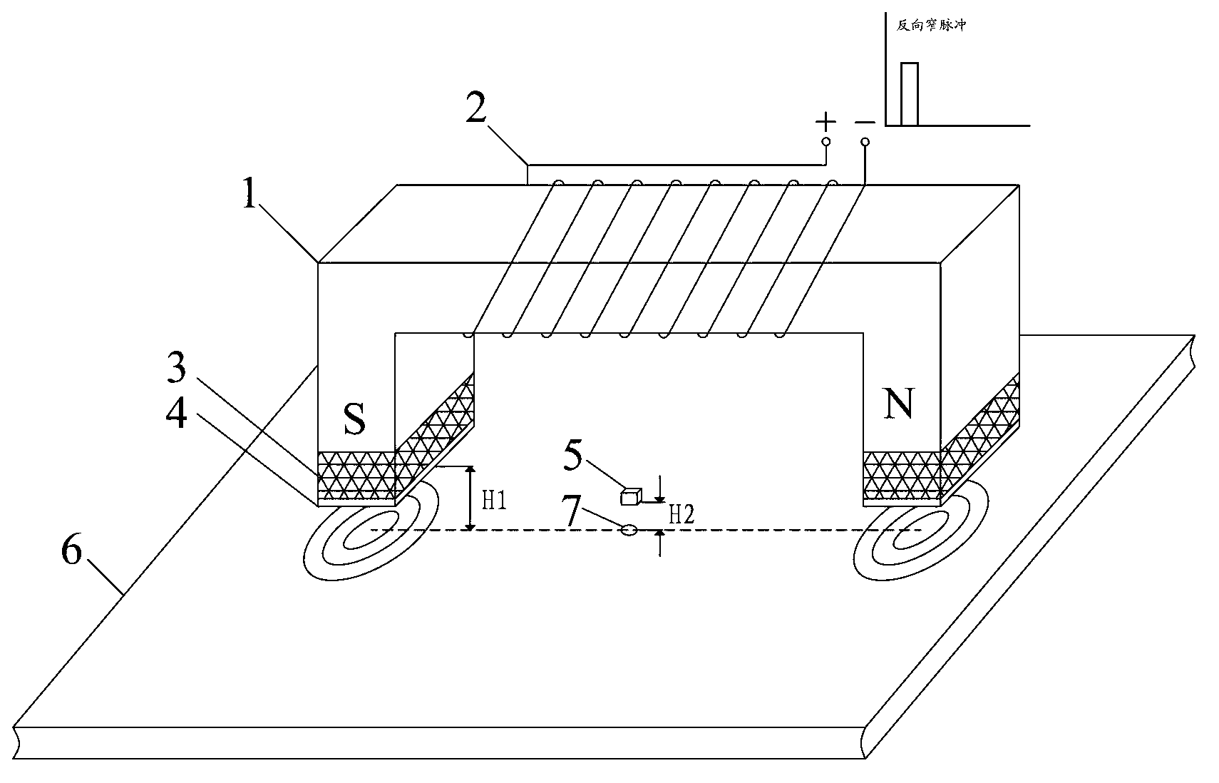
[0031] refer to figure 1 , a permanent magnet and pulsed eddy current compound magnetic flux leakage detection method of the present invention, the detection probe used is mainly composed of a U-shaped yoke 1, an excitation coil 2, a permanent magnet 3, a pole piece 4, and a detection element 5. The exciting coil 2 is wound around the middle section of the U-shaped yoke 1 . The permanent magnets 3 are fixed on both ends of the U-shaped yoke 1 . The pole piece 4 is fixed under the permanent magnet 3, and with a certain lift-off value H 1 placed above the ferromagnetic material 6 to be tested. The detection element 5 is fixed in the middle of the two magnetic poles of the U-shaped yoke, and with a certain lift-off value H 2 placed above the ferromagnetic material 6 to be tested. The detection element 5 adopts a magnetic sensitive sensor, which can be a Hall element.

[0032] The de...


PUM

PropertyMeasurementUnit
thicknessaaaaaaaaaa

Abstract

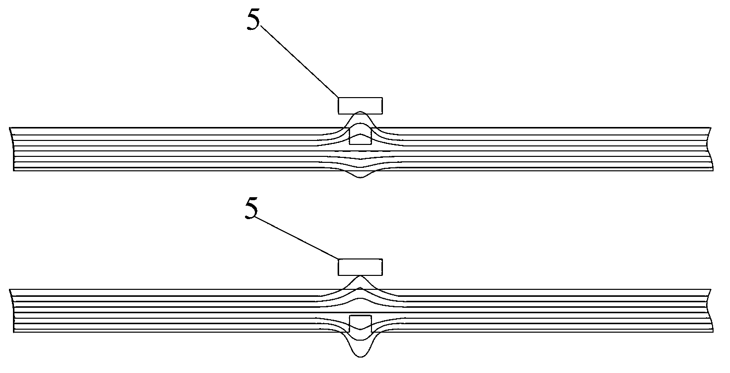
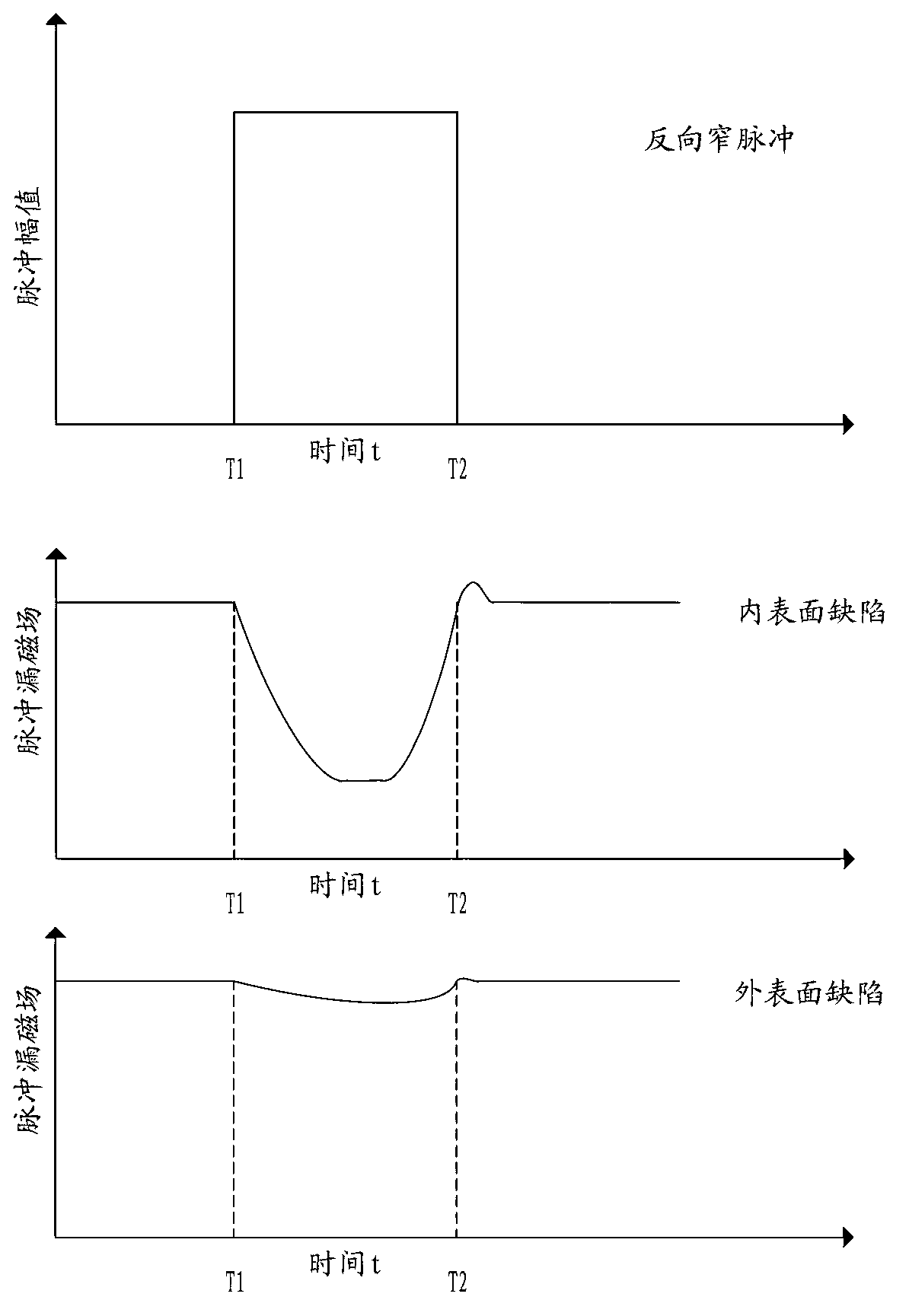
The invention relates to a permanent-magnet and pulsed-eddy-current composite magnetic flux leakage detection method. With the method provided by the invention, defects on inner and outer surfaces can be effectively identified. The method belongs to the field of nondestructive test. With the effect of a permanent magnet, a ferromagnetic material requiring detection is magnetization into a local saturation state; if a detected magnetic flux leakage signal is larger than a preset intensity threshold B1, the ferromagnetic material has a defect; a reverse narrow pulse signal is applied to a excitation coil, such that the excitation coil generates a pulsed magnetic field, and pulsed eddy current is formed on the inner surface of the ferromagnetic material below two poles of a U-shaped magnetic yoke; at the time, if a detected leakage field intensity pulsation value is larger than a preset pulsation threshold B2, the defect is positioned on the inner surface of the ferromagnetic material; otherwise, the defect is positioned on the outer surface of the ferromagnetic material. The method provided by the invention has the advantages of simple hardware structure, low energy consumption, and convenient and fast signal processing.

Description

technical field [0001] The invention proposes a magnetic flux leakage detection method, especially a magnetic flux leakage detection method combined with permanent magnets and pulsed eddy currents, which realizes the discovery of surface defects of ferromagnetic materials and the identification of inner and outer surface defects, and belongs to the technical field of nondestructive testing. Background technique [0002] With the development of science and technology, there are more and more non-destructive testing methods, which are suitable for different testing occasions, but the most commonly used are the five conventional testing techniques of radiographic testing, eddy current testing, magnetic flux leakage testing, ultrasonic testing and penetration testing. As one of the five conventional nondestructive testing techniques, magnetic flux leakage testing is widely used in the testing of ferromagnetic materials. Compared with other non-destructive testing methods, it has...

Claims


Application Information

Patent Timeline
Patent Type & Authority Applications(China)
IPC IPC(8): G01N27/85G01N27/90
Inventor 吴德会张忠远柳振凉夏晓昊
Owner XIAMEN UNIV
Learn More