Dual-model lane line identification method based on dynamic area division

A lane line recognition and dynamic area technology, applied in character and pattern recognition, instruments, computer components, etc., can solve problems such as poor lane line accuracy, large algorithm calculations, and insufficient area planning

Inactive Publication Date: 2013-06-26
BEIJING INSTITUTE OF TECHNOLOGYGY
View PDF2 Cites 62 Cited by
  • Summary
  • Abstract
  • Description
  • Claims
  • Application Information

AI Technical Summary

Problems solved by technology

[0004] The purpose of the present invention is to propose a dual-model lane line recognition method based on dynamic area division to improve image Preprocessing effect;

Method used


Image

  • Dual-model lane line identification method based on dynamic area division
  • Dual-model lane line identification method based on dynamic area division
  • Dual-model lane line identification method based on dynamic area division

Examples


Embodiment Construction

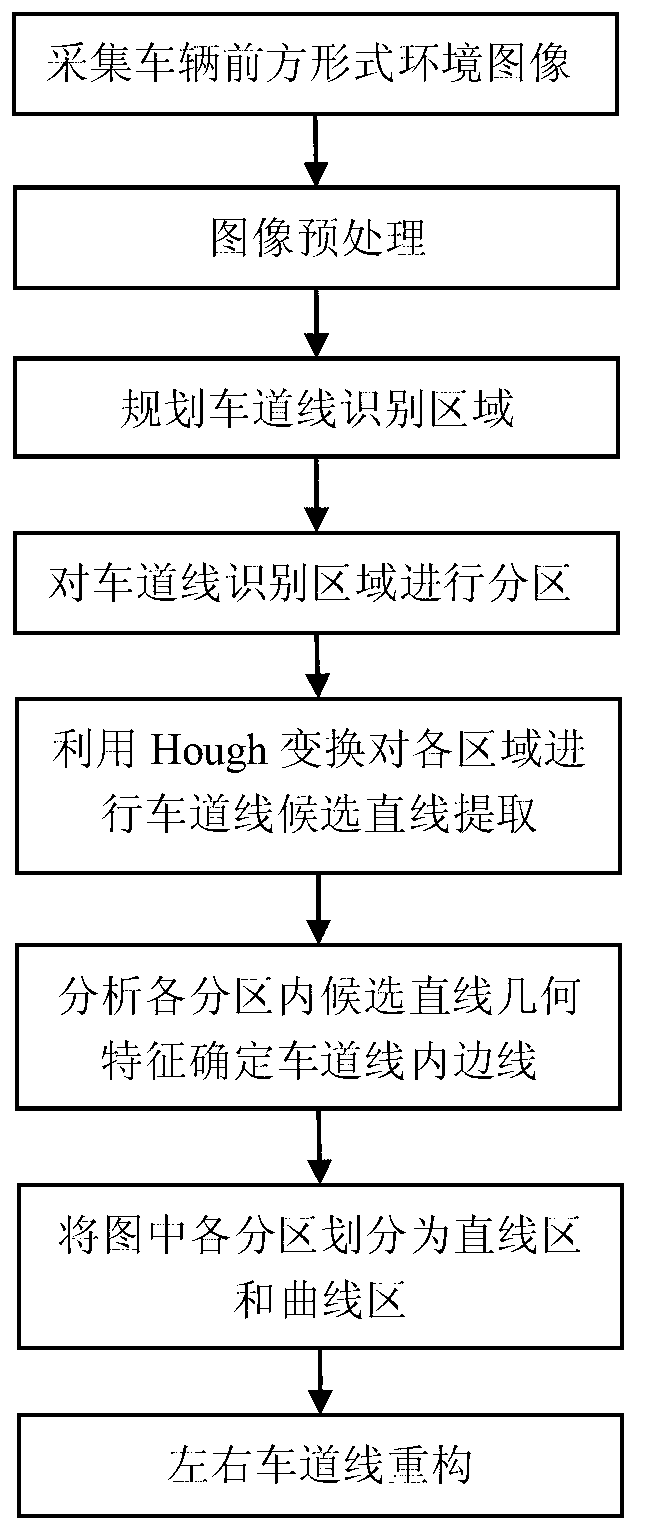
[0056] See attached figure 1 , a dual-model lane line recognition method based on dynamic area division, which includes the following steps:

[0057] Step 1, collecting the original image I of the environment in front of the vehicle;

[0058] During the driving process of the vehicle, the original image I of the driving environment in front of the vehicle is collected by the image sensor installed under the front windshield of the vehicle, and the upper left corner of the original image I is set as the origin of the image coordinate system, and the horizontal direction to the right is the positive direction of the x-axis. Vertically downward is the positive direction of the y-axis, and the original image I is as Figure 5 As shown, the original image I is a matrix of 752 × 480, and each element in the matrix represents a gray value;

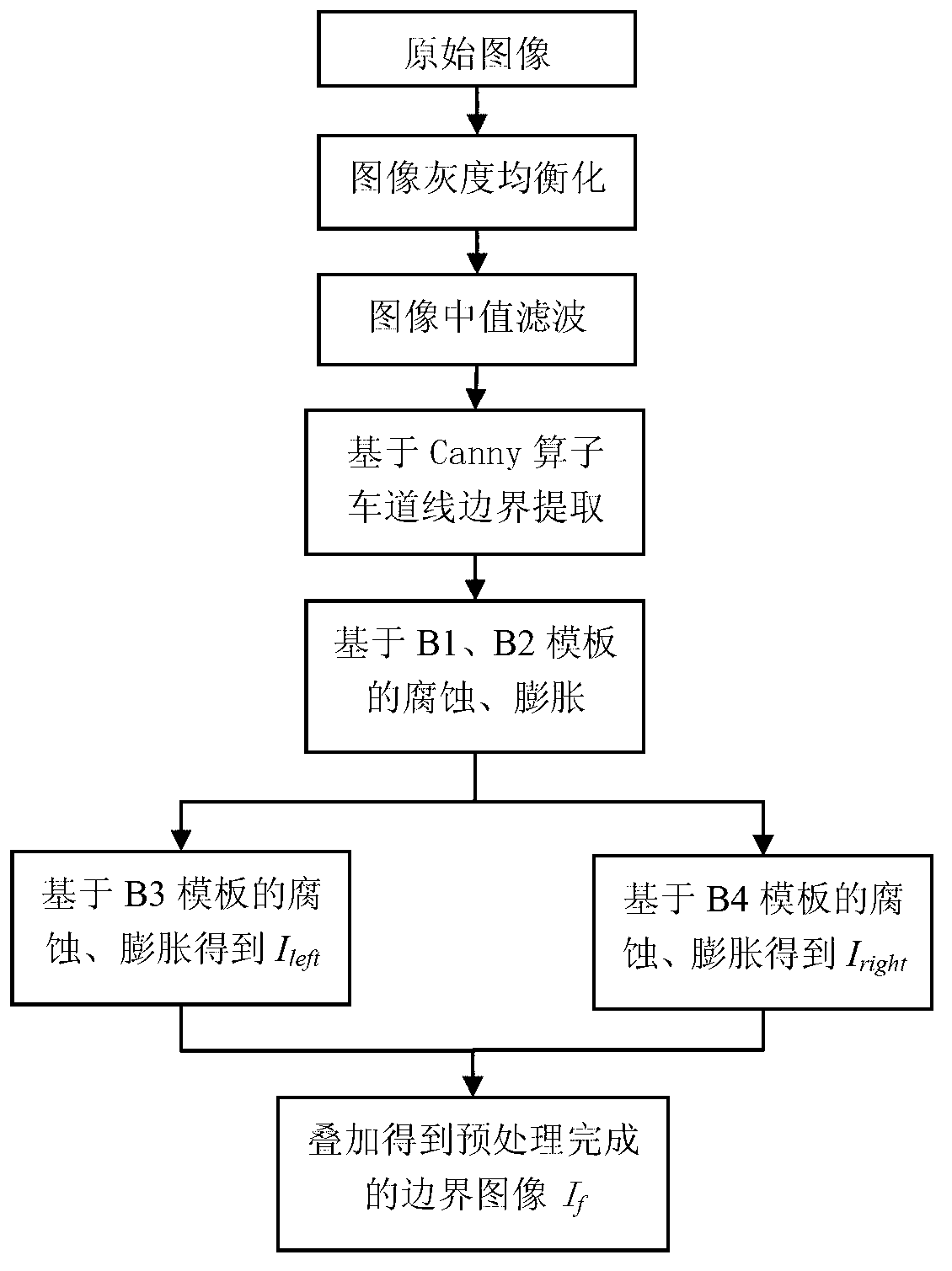
[0059] See attached figure 2 , step 2, the original image I is preprocessed, and the specific steps include:

[0060] 2.1 Perform gray leve...


PUM


Abstract

The invention belongs to the technical field of vehicle aided driving and in particular relates to an intelligent lane line identification method. A dual-model lane line identification method based on dynamic area division comprises the following steps of: 1, collecting an original image I of the environment in front of a vehicle; 2, preprocessing the original image I; 3, planning a lane line identification area; 4, dividing the lane line identification area; 5, identifying the divided areas and extracting a straight line cluster from each area; 6, analyzing the geometrical characteristics of candidate straight lines in each divided area and determining the inner edge line of the lane line; 7, dividing each divided area in the map into a straight line area and a curve area; and 8, reconfiguring left and right lane lines. Compared with other similar methods, the method has the advantages of greatly improving the accuracy and the robustness of lane line detection and tracking.

Description

technical field [0001] The invention belongs to the technical field of vehicle auxiliary driving, and in particular relates to an intelligent recognition method of lane lines. Background technique [0002] Lane lines are the most basic traffic signs and also the most basic constraints when a car is driving. The lane line recognition system based on machine vision is an important part of the intelligent transportation system. Blind Spot Information System) and other advanced assisted driving systems of automobiles are also the basic prerequisite for obstacle recognition. [0003] At present, the lane line recognition system based on machine vision mainly acquires the image of the road ahead through image sensors such as front-view cameras installed on the vehicle, and then extracts the lane line from the image. When extracting lane lines, commonly used algorithms include Hough transform, template matching, and region growing methods. The difficulty of the algorithm lies in...

Claims


Application Information

Patent Timeline
IPC IPC(8): G06K9/00
Inventor 齐志权王宝锋马国成
Owner BEIJING INSTITUTE OF TECHNOLOGYGY
Why Eureka
Try Eureka