
Intelligent high-voltage thyristor switched capacitor (TSC) reactive compensation device

A compensation device, high voltage technology, applied in reactive power adjustment/elimination/compensation, harmonic reduction devices, flexible AC transmission systems, etc., can solve the problems of reducing the average service life of capacitor banks, inaccurate and fast, excessive inrush current, etc. , to achieve the effect of no switching oscillation problem and low inrush current

Inactive Publication Date: 2013-06-26
SICHUAN EXTREME ELECTRIC CONTROL SYST MFG
View PDF2 Cites 8 Cited by
  • Summary
  • Abstract
  • Description
  • Claims
  • Application Information

AI Technical Summary

Problems solved by technology

Due to the long and erratic mechanical switching time of MSC, it cannot be switched on accurately and quickly at the zero-crossing point of the voltage, which may easily cause excessive inrush current and damage the capacitor bank.
And when the capacitor bank is disconnected, it is easy to generate an arc, which will cause the mechanical switch contacts to be arced and burned, which will bring unnecessary trouble to the maintenance personnel.
However, most of the current TSC devices have not realized the cyclic switching of capacitor banks, and there is a problem of switching oscillation, which will undoubtedly reduce the average service life of capacitor banks and cause system instability.

Method used


Image

  • Intelligent high-voltage thyristor switched capacitor (TSC) reactive compensation device
  • Intelligent high-voltage thyristor switched capacitor (TSC) reactive compensation device
  • Intelligent high-voltage thyristor switched capacitor (TSC) reactive compensation device

Examples


Embodiment Construction

[0013] Hereinafter, the invention will now be described more fully with reference to the accompanying drawings, in which various embodiments are shown. However, this invention may be embodied in many different forms and should not be construed as limited to the embodiments set forth herein. Rather, these embodiments are provided so that this disclosure will be thorough and complete, and will fully convey the scope of the invention to those skilled in the art.

[0014] Below in conjunction with embodiment the present invention is further described.

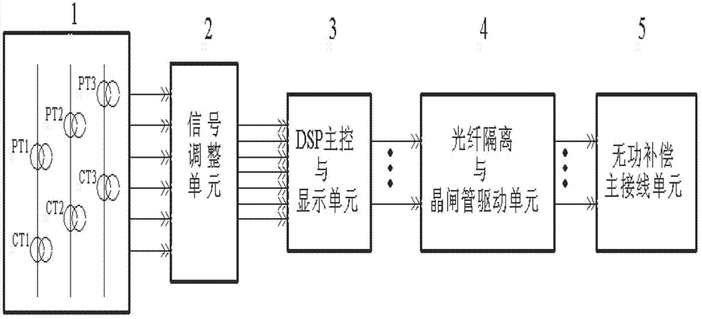
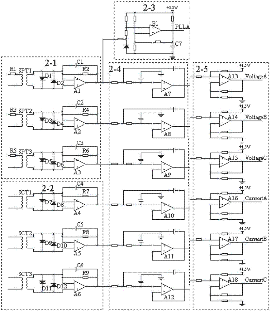
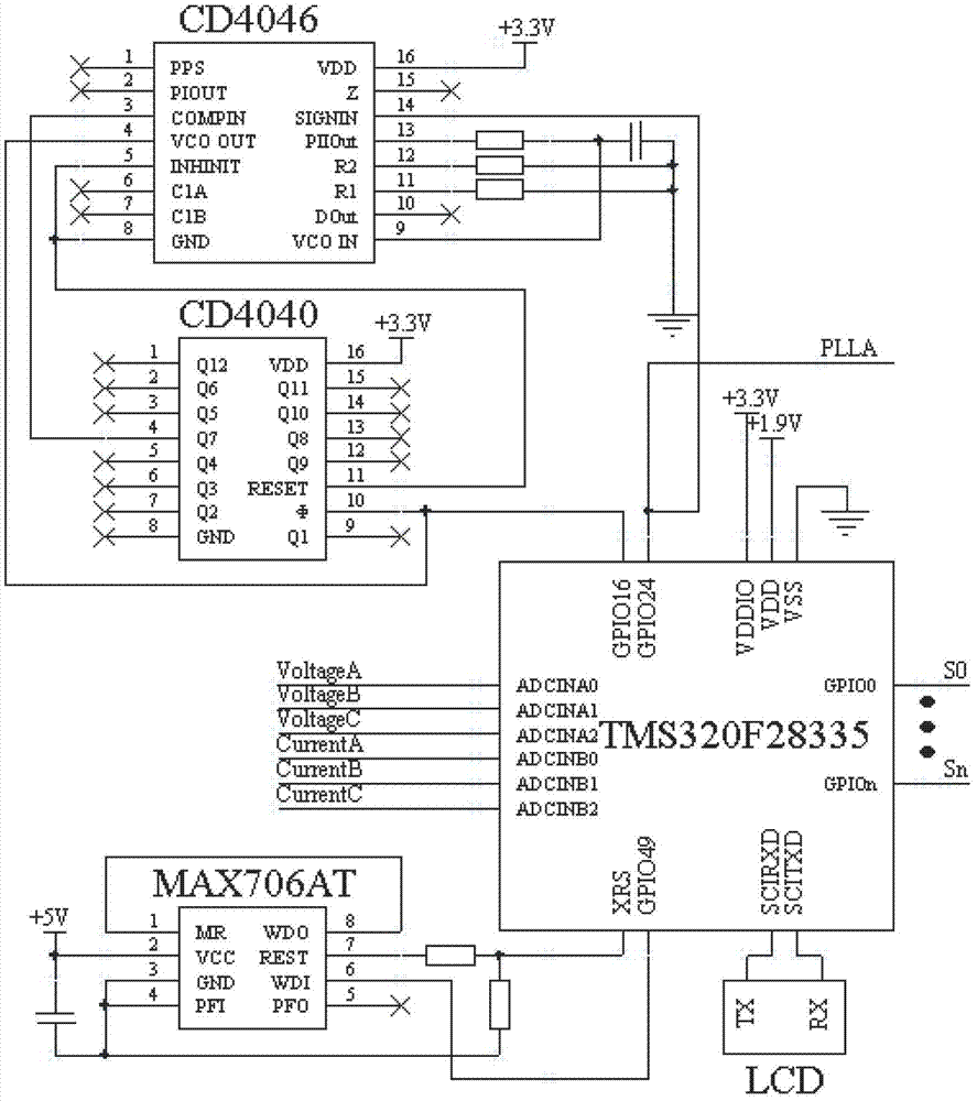
[0015] see figure 1 , 2 , 3, 4, 5, the intelligent TSC reactive power compensation device includes voltage and current transformer (1), signal adjustment unit (2), DSP main control and display unit (3), optical fiber isolation and thyristor drive unit (4) and wireless The power compensation main wiring unit (5); the signal adjustment unit (2) includes a voltage amplitude adjustment module (2-1), a current amplitude adjustment mo...


PUM


Abstract

The invention relates to an intelligent high-voltage thyristor switched capacitor (TSC) reactive compensation device which comprises a potential current transformer, a signal adjusting unit, a digital signal processor (DSP) main control and display unit, an optical fiber isolation and thyristor driving unit and a reactive compensation main wiring unit, wherein the signal adjusting unit comprises a voltage amplitude adjustment module, a current amplitude adjustment module, a synchronous square wave generation module, a filter module and a lifting module which are sequentially connected; outputs of the synchronous square wave generation module and the lifting module are respectively connected with an input capture hole and an analog-to-digital (AD) conversion hole of a DSP in the DSP main control and display unit; an output input / output (IO) port of the DSP in the DSP main control and display unit is connected with an input end of an optical fiber transmitter of the optical fiber isolation and thyristor driving unit; and an output end of the optical fiber isolation and thyristor driving unit is connected with a gate pole and a cathode of a thyristor in the reactive compensation main wiring unit. The intelligent high-voltage TSC reactive compensation device realizes zero-crossing voltage input and capacitor bank cyclical switchover, does not have the problem of switching oscillation, and is used for reactive compensation of transformer substations in the industries such as metallurgy, steel and coal.

Description

technical field [0001] The invention relates to a reactive power compensation device, in particular to a TSC type reactive power compensation device, and belongs to the technical field of reactive power compensation. Background technique [0002] At present, most reactive power compensation devices in my country are mechanical switch switching capacitor MSC and thyristor switching capacitor TSC. Due to the long and erratic mechanical switching time of MSC, it cannot be switched on accurately and quickly at the voltage zero crossing point, which may easily cause excessive inrush current and damage the capacitor bank. And when the capacitor bank is disconnected, an electric arc is easily generated, causing the mechanical switch contacts to be arced and burned, which brings unnecessary troubles to the maintenance personnel. However, most of the current TSC devices do not realize the cyclic switching of the capacitor bank, and there is a problem of switching oscillation, which ...

Claims


Application Information

Patent Timeline
IPC IPC(8): H02J3/18H02J3/01
CPCY02E40/10Y02E40/40
Inventor 黄中军王奔范月明张翔冯峥
Owner SICHUAN EXTREME ELECTRIC CONTROL SYST MFG
Learn More