Wire type heating wire device

A technology of heating wires and wires, applied in the direction of heating element materials, heating element shapes, etc., can solve problems such as uneconomical, inability to form a line short circuit prevention circuit, failure of the temperature control part, etc., and achieve the effect of preventing smoke

Inactive Publication Date: 2013-06-26
HONGKONG TACHIBANA ELECTRONICS
View PDF9 Cites 4 Cited by
  • Summary
  • Abstract
  • Description
  • Claims
  • Application Information

AI Technical Summary

Problems solved by technology

[0054] However, even if the above preventive measures are taken, the temperature control part may fail. In order to prepare for the situation where the heat-sensitive polymer layer 3d is melted and a short circuit occurs between the heating wire 2d and the overheating detection wire 6d, a line-to-line short-circuit protection circuit, but as Figure 7 As shown, the circuit connection for line-to-line short-circuit protection that can adhere to the above-mentioned main purpose of "signal separation" can only be constructed as in the image 3 and Figure 5 As in the case of using the popular single-wire electric heating wire 102 described in , the line-to-line short-circuit protection operation with less fluctuation cannot be obtained.
[0055] Of course, with regard to the overheating detection wire 6d, it can also be used as a special device for short-circuit protection between lines with high sensitivity that flows through the AC half-wave current in two paths like the two-wire type, but it cannot constitute the overheating signal as the main purpose. The prevention circuit of the line short circuit caused by the
Therefore, as a means to achieve the purpose of Patent Document 5, the insulation coating treatment of the temperature detection wire 4d does not need to perform its function, so it is extremely uneconomical to use the overheat detection wire as a dedicated device for short circuit detection wires in the structure of Patent Document 5

Method used


Image

  • Wire type heating wire device
  • Wire type heating wire device
  • Wire type heating wire device

Examples


Embodiment Construction

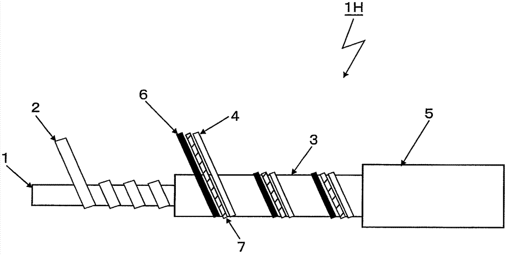
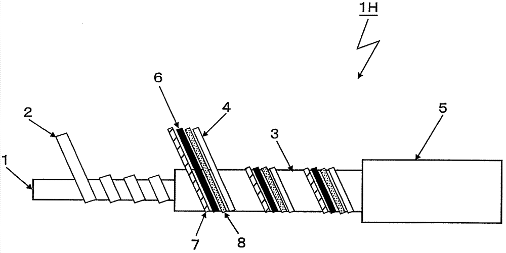
[0100] Embodiments of the electric heating wire according to the present invention will be described in detail below with reference to the drawings and the like. In addition, this invention is not limited to the following unless it deviates from the summary. Figure 1A One end of the wire-shaped heating wire 1H according to the embodiment of the present invention is shown, and the insulating coating layer, the polymer layer, and the like are partially omitted.

[0101] The wire-shaped heating wire 1H is composed of: a winding core 1 of fiber bundles such as glass fibers or polyester fibers; a heating wire 2 formed by helically winding a rectangular conductor of copper or copper alloy around the outer periphery of the winding core 1; A polymer layer 3 formed by extruding a thermosensitive polymer resin on the outer periphery of the heating wire 2; At least one insulated wire 7 between the wires; an insulating coating layer 5 formed by extruding polyvinyl chloride or the like o...


PUM


Abstract

The invention provides a wire type heating wire device, which is a single-line wire type heating wire. Insulating wires, temperature detecting wires and short circuit detecting wires are alternately arranged on the periphery of a high polymer layer. The wires are co-stranded and spirally wound so as to make a temperature control circuit and an inter-wire short circuit protecting circuit separated. In this way, inter-wire short circuit protection functions characterized by high precision, stable temperature control function, alleviated fluctuation and high safety are acquired. The economical effects are also great. Heating wires are wound on a roll core in a spiral way. The high polymer layer is formed on the periphery of the heating wires. At least one insulating wire serves as the temperature detecting wire and the short circuit detecting wire of a conductor and is alternately arranged on the periphery of the conductor. The wires are spirally wound in a co-strand way. Furthermore, an insulating coating layer is formed thereon. The temperature detecting wire and the short circuit detecting wire are separated spatially. Therefore, the temperature control by the temperature detecting wires and the inter-wire short circuit protection by the short circuit detecting wires are respectively independent and performed in a high-precision and non-fluctuation way.

Description

technical field [0001] The invention relates to a wire-shaped heating wire device used in planar heating appliances such as electric heating blankets and electric heating carpets. Background technique [0002] In general, wire-shaped heating wire devices used in surface heating appliances such as electric blankets and electric heating carpets are well known. A structure called a two-wire type consisting of a wire-shaped heating wire, and its structure is as follows image 3 shown. [0003] In this figure, the wire-like sensor wire 100 is composed of: a winding core 1a of a fiber bundle such as polyester fiber; an inner electrode wire 2a formed by spirally winding a copper or copper alloy conductor around the outer periphery of the winding core 1a; Thermally sensitive polymer layer 3a formed by extruding thermosensitive polymer resin on the outer periphery of inner electrode wire 2a; outer electrode wire formed by spirally winding copper or copper alloy conductors on the out...

Claims


Application Information

Patent Timeline
Patent Type & Authority Applications(China)
IPC IPC(8): H05B3/56H05B3/10
Inventor 野村卓志朝仓正博
Owner HONGKONG TACHIBANA ELECTRONICS
Why Eureka
Try Eureka