
Side coupling cavity structure and standing wave electron linear accelerator

A side coupling cavity and coupling cavity technology, which is applied in the field of medical standing wave electron linear accelerators, can solve the problems of complex devices, serious bellows life, problems, etc., and achieve the effect of easy replacement

Inactive Publication Date: 2013-06-26
MIAN YANG GAO XIN QU TWIN PEAK TECH DEV
View PDF7 Cites 7 Cited by
  • Summary
  • Abstract
  • Description
  • Claims
  • Application Information

AI Technical Summary

Problems solved by technology

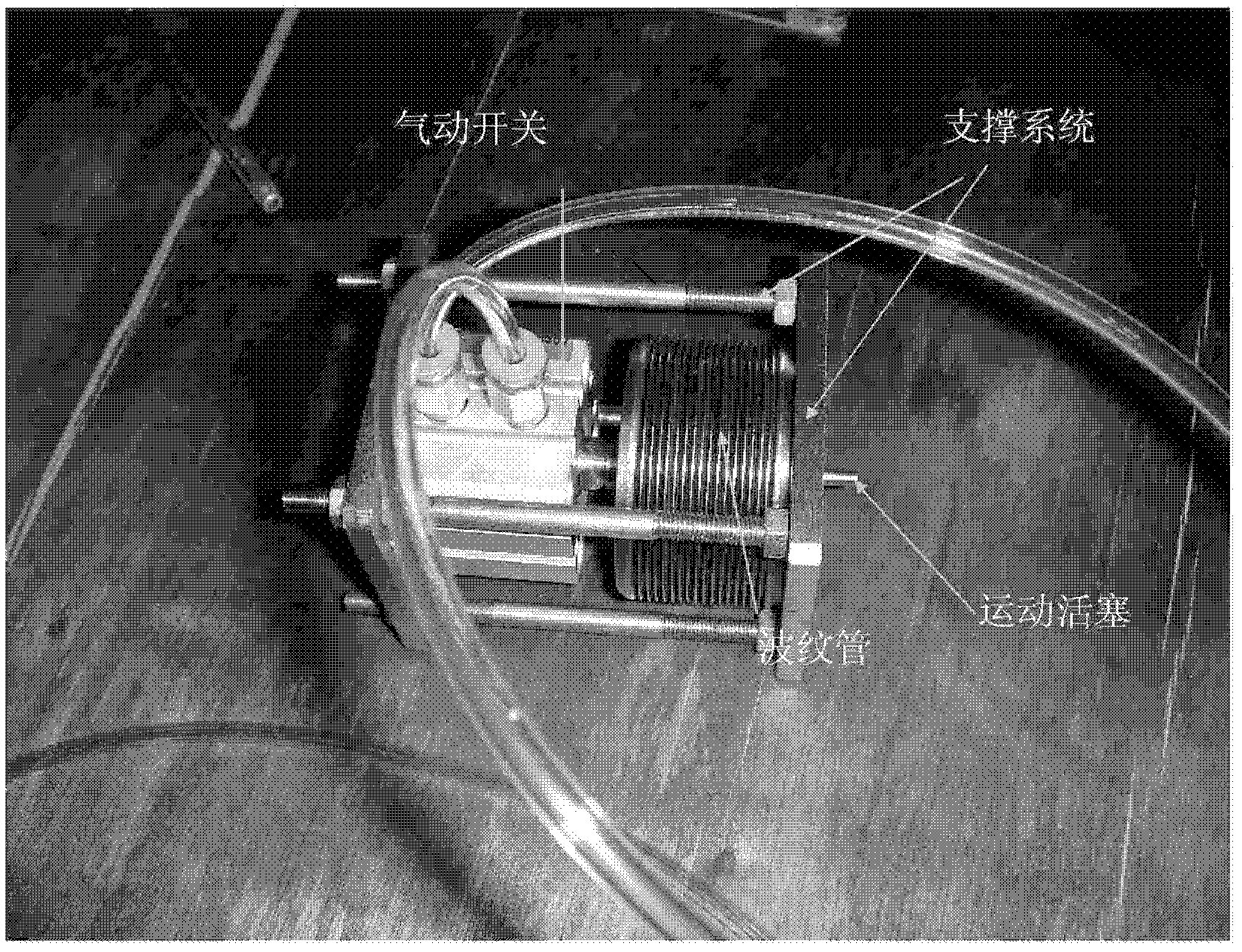
[0005] First of all, since the area where the piston moves in the side coupling cavity 2 is a part of the acceleration tube, it is in a high vacuum state, which makes the whole device very complicated, and there are many difficulties in the process
Especially for small medical acceleration tubes, with a fully sealed structure, they have to go through long-term high-temperature exhaust treatment, which will affect the service life of the bellows
[0006] Secondly, the bellows have a certain compression ratio, and the whole device is difficult to miniaturize
[0007] Finally, the fast reciprocating motion makes bellows lifespan a serious issue

Method used


Image

  • Side coupling cavity structure and standing wave electron linear accelerator
  • Side coupling cavity structure and standing wave electron linear accelerator
  • Side coupling cavity structure and standing wave electron linear accelerator

Examples


Embodiment Construction

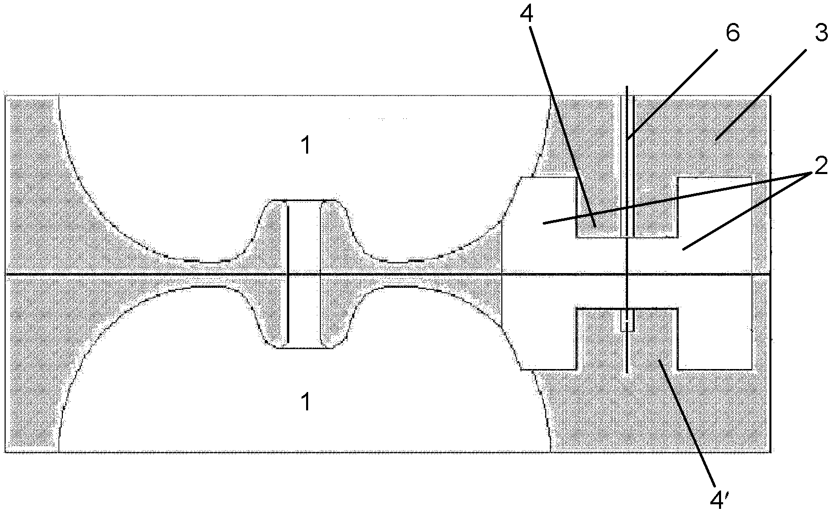
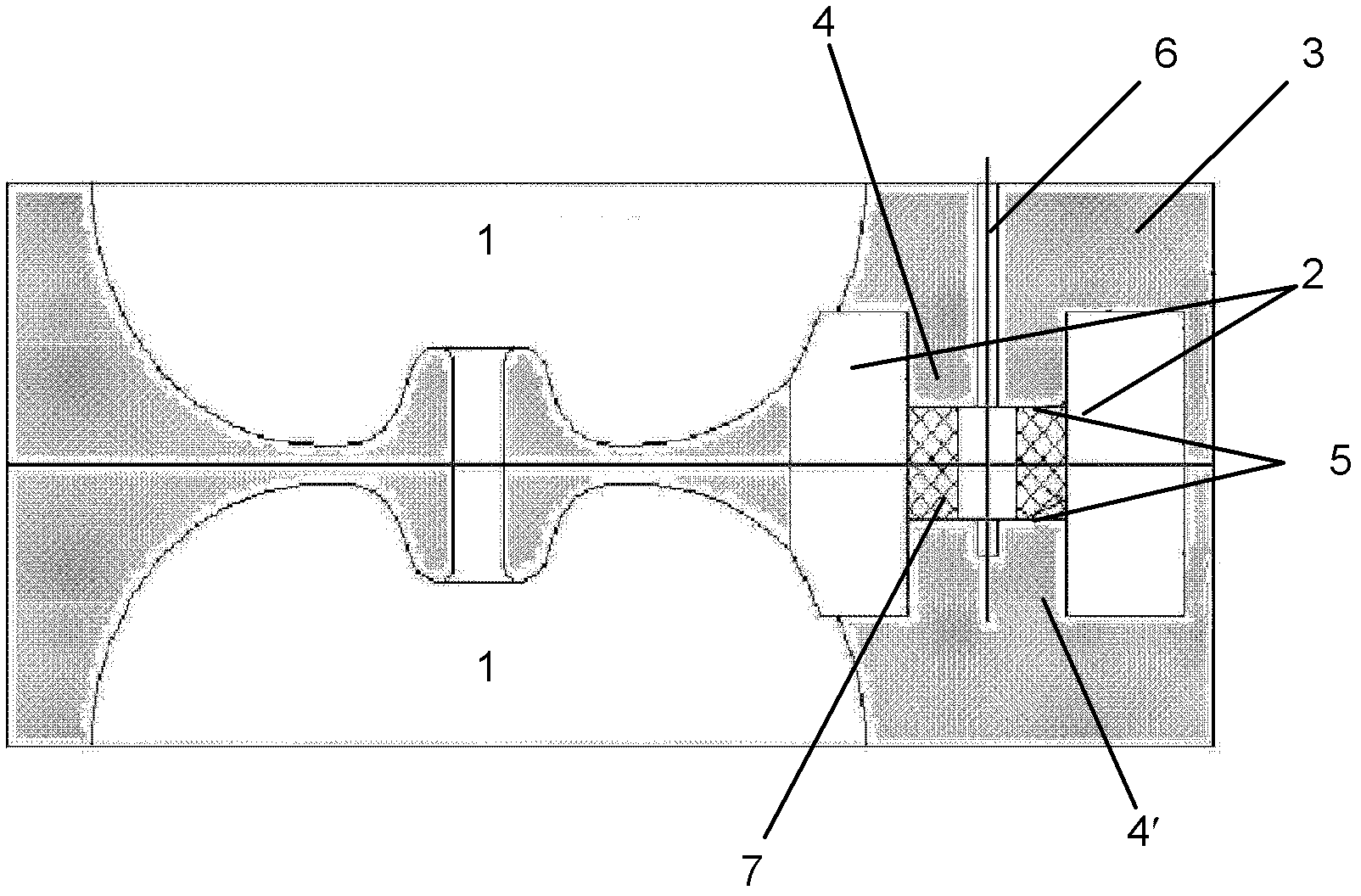
[0017] Such as image 3 As shown, according to the first embodiment of the present invention, a ceramic-sealed side-coupled cavity structure is proposed. The side coupling cavity 2 is arranged on one side of the accelerating cavity 1 in such a manner as to be mutually coupled with the accelerating cavity 1 . The side coupling cavity 2 is formed as follows: The side coupling cavity 2 is divided into two chambers by an upper coupling cavity column 4 and a lower coupling cavity column 4' protruding from the cavity body 3. Near the center of the upper coupling cavity column 4 and the lower coupling cavity column 4', a piston channel 6 for inserting and withdrawing the piston into and withdrawing from the side coupling cavity is provided in a manner penetrating through the cavity body 3. When the piston extends into the side coupling cavity 2, it will detune the side coupling cavity 2, and the side coupling cavity 2 will work normally when the piston is retracted.

[0018] As one...


PUM


Abstract

The invention provides a side coupling cavity structure and a standing wave electron linear accelerator where the side coupling cavity structure is used. The side coupling cavity structure is arranged on one side of an accelerating cavity and comprises a cavity, an upper coupling cavity column, a lower coupling cavity column, a piston channel and ceramic rings, wherein the upper coupling cavity column and the lower coupling cavity column are protruded out of the cavity; the piston channel is arranged beside the position of the center of the upper coupling cavity column and the lower coupling cavity column and penetrates through the cavity; and end face parts of the ceramic rings are metalized, and the ceramic rings are fixed on the upper coupling cavity column and the lower coupling cavity column through the metalized end face parts by seal welding. Due to the fact that a moving area of a piston in the side coupling cavity is not a vacuum area of an accelerating tube, a bellows does not need using, and not only is a whole device miniaturized, but also the pneumatic piston can be replaced conveniently without influencing functions of the accelerating tube. In addition, due to the fact that a ceramic material wall of a ceramic cylinder is thin, the influence on a capacitor caused by the inserted ceramic cylinder can be further reduced after the ceramic cylinder is inserted into the cavity.

Description

technical field [0001] The invention relates to a ceramic sealed side coupling cavity structure, in particular to a standing wave electron linear accelerator using the side coupling cavity structure, in particular to a standing wave electron linear accelerator for medical use. Background technique [0002] Standing wave electron linear accelerators have been widely used in radiation therapy, and 'guided beam radiation therapy' (IGRT) is the main direction in recent years. In the invention patent "phase (energy) switch - standing wave electron linear accelerator" (CN1649469), a new type of phase (energy) switch is proposed. [0003] In order to realize the function described in the invention patent "Phase (Energy) Switch - Standing Wave Electron Linear Accelerator" (CN1649469), it is necessary to design a piston that moves back and forth quickly in the side coupling cavity. figure 1 A pneumatic piston that can be used in the above-mentioned invention is shown. And as figur...

Claims


Application Information

Patent Timeline
Patent Type & Authority Applications(China)
IPC IPC(8): H05H7/18H05H9/04
Inventor 姚充国
Owner MIAN YANG GAO XIN QU TWIN PEAK TECH DEV
Learn More