
Method for correcting fluorescent sensor, and fluorescent sensor

A technology of fluorescence sensor and calibration method, which is applied in the calibration of fluorescence sensor and the field of fluorescence sensor, and can solve the problems such as inability to measure the concentration of analyte

Inactive Publication Date: 2013-06-26
OLYMPUS CORP +1
View PDF1 Cites 1 Cited by
  • Summary
  • Abstract
  • Description
  • Claims
  • Application Information

AI Technical Summary

Problems solved by technology

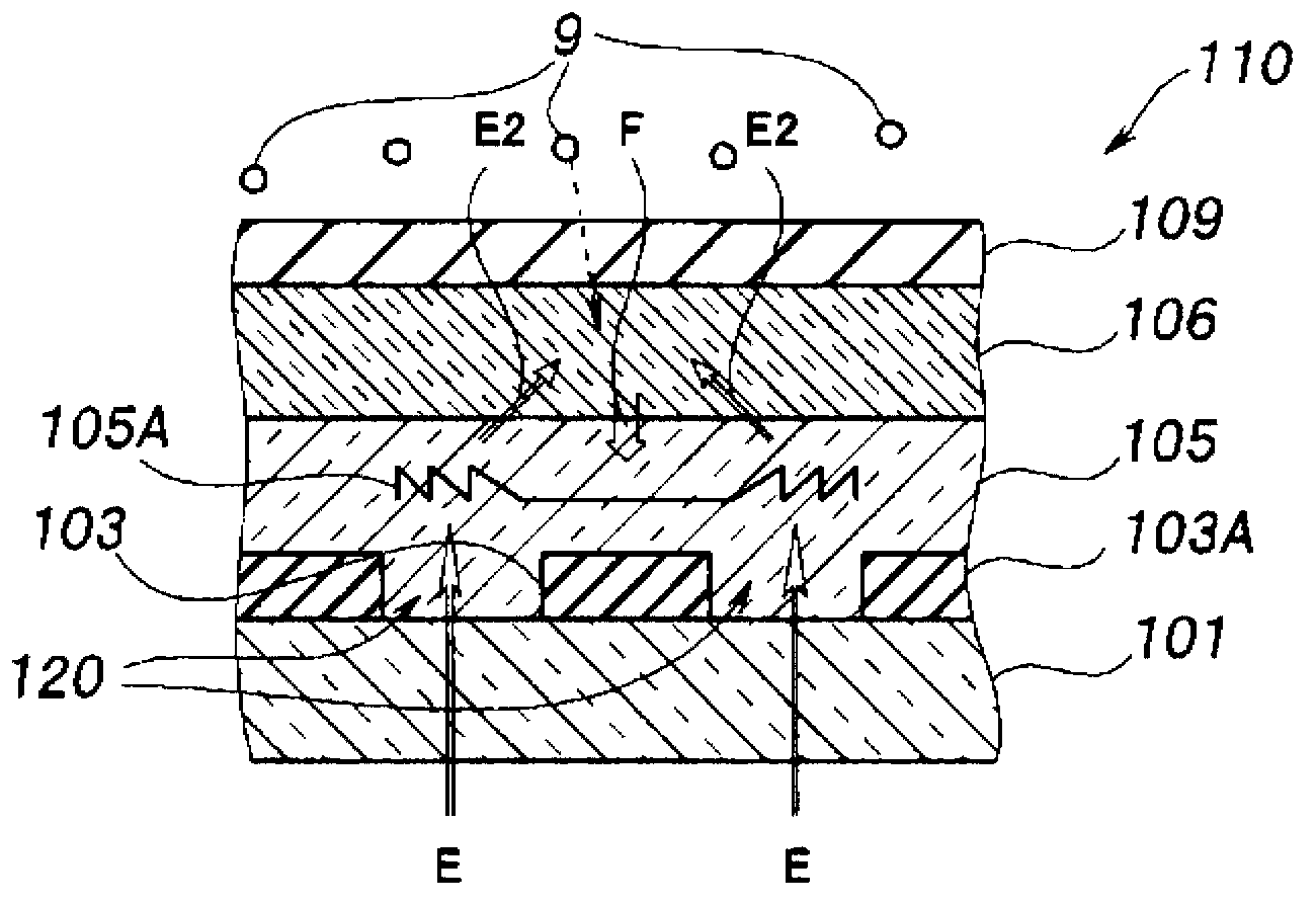
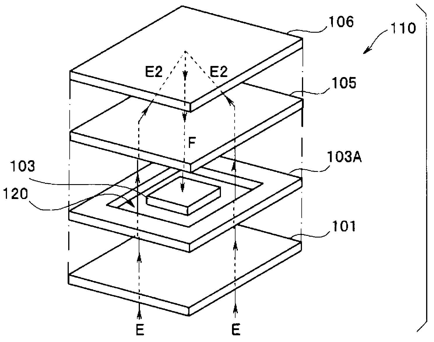
In this way, since the excitation light detection signal overlaps with the fluorescence detection signal, the detection signal from the photoelectric conversion element 103 may not be able to measure the correct analyte concentration.

Method used


Image

  • Method for correcting fluorescent sensor, and fluorescent sensor
  • Method for correcting fluorescent sensor, and fluorescent sensor
  • Method for correcting fluorescent sensor, and fluorescent sensor

Examples


Embodiment Construction

[0022]

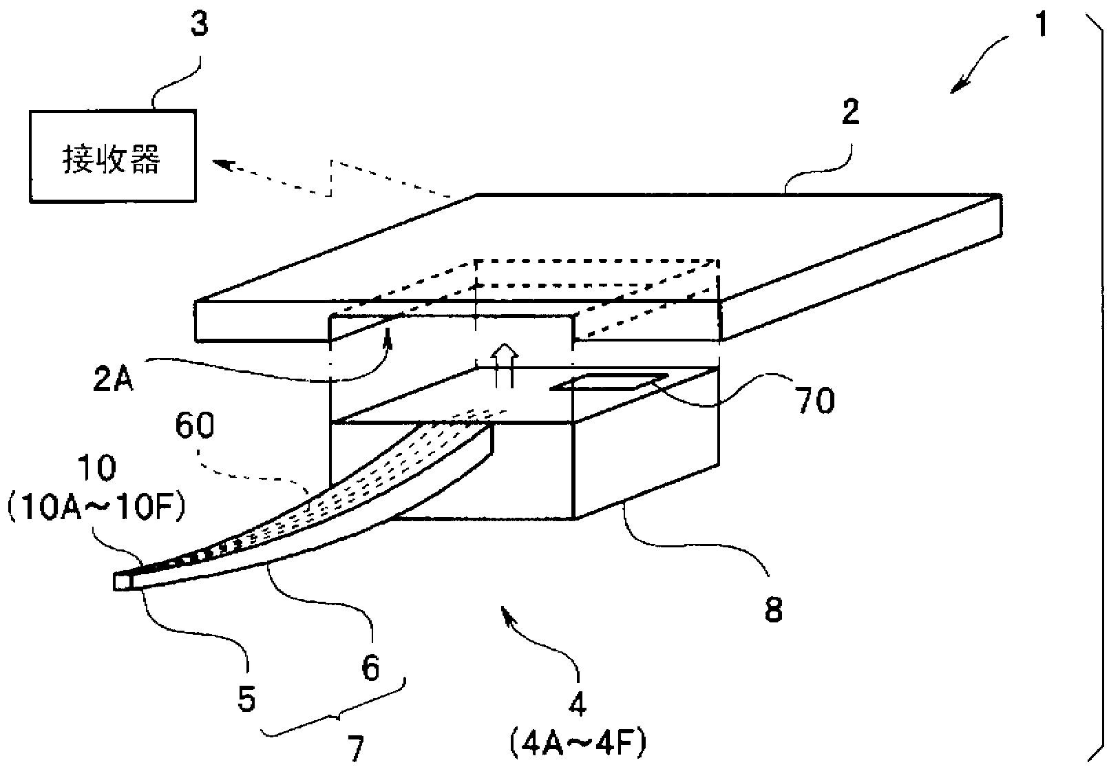
[0023] Such as image 3 As shown, the needle-type fluorescence sensor 4 including the fluorescence sensor 10 according to the embodiment of the present invention constitutes the sensor system 1 together with the main body 2 and the receiver 3 .

[0024] That is, the sensor system 1 has a needle-type fluorescent sensor 4 , a main body 2 , and a receiver 3 that receives and stores a signal from the main body 2 . The transmission and reception of signals between the main body 2 and the receiver 3 is performed wirelessly or by wire.

[0025] The needle-type fluorescence sensor 4 is provided with: a needle portion 7 having a needle front end portion 5 and an elongated needle body portion 6 including a fluorescence sensor 10 as a main functional portion; Integrated connector part 8. The needle tip portion 5, the needle body portion 6, and the connector portion 8 may also be integrally formed of the same material.

[0026] The connector part 8 is detachably fitted into ...


PUM


Abstract

A method for correcting a fluorescent sensor in the embodiment of the present invention is provided with: a first detection signal acquiring step wherein a first detection signal is acquired at a first temperature using a fluorescent sensor (10), which is provided with an LED element (12), an indicator layer (16), and a PD element (13) that outputs a detection signal having an excitation light detection signal superimposed on a fluorescent detection signal, and which has a temperature detecting function and a temperature adjusting function; a second detection signal acquiring step wherein a second detection signal is acquired at a second temperature when an analyte quantity is equivalent to that in the first detection signal acquiring step; a correction coefficient calculating step wherein a correction coefficient for correcting the fluorescent detection signal is calculated on the basis of the first detection signal and the second detection signal; and a correcting step wherein subsequent detection signals are corrected using the correction coefficient and a temperature detection signal.

Description

technical field [0001] Embodiments of the present invention relate to a fluorescence sensor for measuring the concentration of an analyte and a method for calibrating the above-mentioned fluorescence sensor, and particularly to a fluorescence sensor and the above-mentioned fluorescence sensor as a microscopic fluorescence spectrophotometer manufactured using semiconductor manufacturing technology and MEMS technology. Calibration method. Background technique [0002] Various analytical devices have been developed for determining the presence or measuring the concentration of an analyte, ie, a substance to be measured, in a liquid. For example, a fluorochrome whose property changes due to the presence of an analyte to generate fluorescence and a solution to be measured containing the analyte are injected into a transparent container of a certain capacity, and measured by irradiating excitation light E and measuring the intensity of fluorescence from the fluorochrome Fluoresce...

Claims


Application Information

Patent Timeline
Patent Type & Authority Applications(China)
IPC IPC(8): G01N21/64G01N21/78
CPCG01N21/6428G01N21/6454G01N2201/1211G01N21/64
Inventor 前江田和也河野弘昌
Owner OLYMPUS CORP
Learn More