
Matching network for transmission circuitry

A technology of output matching network and transmission circuit, which is applied in the field of wireless communication

Active Publication Date: 2013-06-26
CREE INC
View PDF2 Cites 16 Cited by
  • Summary
  • Abstract
  • Description
  • Claims
  • Application Information

AI Technical Summary

Problems solved by technology

[0014] Although the impedance at the center frequency of operation may be considered "ideal" for a given performance criterion, if the impedance matching network 14 is configured and controlled to provide an impedance at any given RF input signal RF IN the center frequency of , and the "ideal" impedance of at least one harmonic associated with that center frequency, the transmission path may be significantly better performing, as shown in Figure 6

Method used


Image

  • Matching network for transmission circuitry
  • Matching network for transmission circuitry
  • Matching network for transmission circuitry

Examples


Embodiment Construction

[0044] The embodiments set forth below represent the necessary information to enable those skilled in the art to practice the disclosure and illustrate the best mode for carrying out the disclosure. Upon reading the following description with reference to the accompanying drawing figures, those skilled in the art will understand the concepts of the disclosure and will recognize applications of these concepts not particularly addressed herein. It should be understood that these concepts and applications fall within the scope of this disclosure and the appended claims.

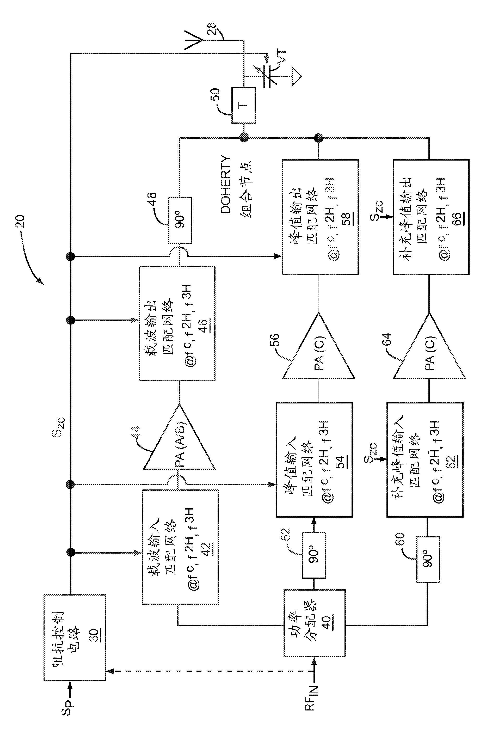
[0045] Referring to FIG. 7 , a transmission circuit 20 is shown according to a first embodiment of the present disclosure. Transmission circuitry 20 includes control and modulation circuitry 22 , power amplification circuitry (PA) 24 , output matching network 26 , antenna 28 and impedance control circuitry 30 . Control and modulation circuitry 22 may represent a separate or integrated control and modulation arc...


PUM


Abstract

The present disclosure relates to transmission circuitry of a wireless communication device. The transmission circuitry includes power amplifier circuitry, an output matching network, and impedance control circuitry. The power amplifier circuitry amplifies a radio frequency (RF) input signal to provide an amplified RF output signal, which is passed through the output matching network and transmitted via one or more antennas. As the center frequency of the RF input signal and conditions of operating parameters change, the impedance control circuitry adjusts the values of one or more variable impedance elements of the output matching network in a desired fashion. The values of the variable impedance elements are adjusted such that the output matching network concurrently and dynamically presents the desired load impedances at the center frequency and at one or more harmonics of the RF input signal to achieve a given performance specification.

Description

[0001] This application claims priority to US Patent Application Serial No. 12 / 917,112, filed November 1, 2010, the entire contents of which are hereby incorporated by reference. technical field [0002] The present disclosure relates to wireless communications, and in particular, to dynamically controlling a variable matching network of a transmission path to operate at the center frequency of a radio frequency (RF) input signal and at one or more harmonics of the center frequency of the RF input signal as operating conditions change. provide the desired impedance. Background technique [0003] In wireless communication systems, designers are often forced to make compromises between competing performance parameters when designing transmission paths for communication devices such as mobile devices or base stations. Referring to FIG. 1, a typical transmission path of a wireless communication device is shown. The transmission path typically includes a control and modulation c...

Claims


Application Information

Patent Timeline
IPC IPC(8): H04B1/04H03H7/40H03F1/56
CPCH03F1/0288H03F1/56H03F3/24H03F2200/222H03F2200/378H03F2200/387H03H7/40H04B1/0458H04B1/04H03H7/38
Inventor C.哈里斯R.S.彭格利
Owner CREE INC
Learn More