Vertical loop device for high-speed wire rod rolling mill

A looper device and high-speed wire rod technology, applied in metal rolling, metal rolling, bending workpieces, etc., can solve the problems of unqualified cold heading performance, batch quality accidents, affecting product quality, etc., and eliminate the phenomenon of wire scraping , prolong the service life, improve the effect of product quality

Inactive Publication Date: 2013-07-03
MAGANG (GROUP) HOLDING CO LTD +1
View PDF7 Cites 4 Cited by
  • Summary
  • Abstract
  • Description
  • Claims
  • Application Information

AI Technical Summary

Problems solved by technology

[0003] The take-up roll and guide roll of the existing vertical looper device are both flat rolls, and the high-speed wire moves in an arc after the take-up roll is set up, because the guide roll cannot guide the rolling piece to the middle position of the vertical looper rolling channel , the looper side plates on both sides of the rolling channel outlet often scratch the surface of the rolled piece, affecting product quality
Especially for the production of high value-added products such as non-annealing, simplified annealing and non-quenched and tempered steel with high cold heading performance, the requirements for the shape of the wire rod during the rolling process are very high, and a small scratch of 0.05mm on the finished product may cause damage to the product. The cold heading performance is unqualified. If there are scratches larger than 0.2mm on the bar in the middle rolling area, it is reflected on the finished product that it is intermittently folded, which is not easy to find with the naked eye, but the rolled product may be a waste product, which can easily cause batch quality accidents.
While the surface of the rolled piece is scratched, a large number of scraping wires will be formed at the looper outlet, and the scraping wires will block the rolled piece and often cause steel stacking accidents

Method used


Image

  • Vertical loop device for high-speed wire rod rolling mill
  • Vertical loop device for high-speed wire rod rolling mill
  • Vertical loop device for high-speed wire rod rolling mill

Examples


Embodiment Construction

[0016] The specific implementation manner of the present invention will be described in further detail below by describing the embodiments with reference to the accompanying drawings.

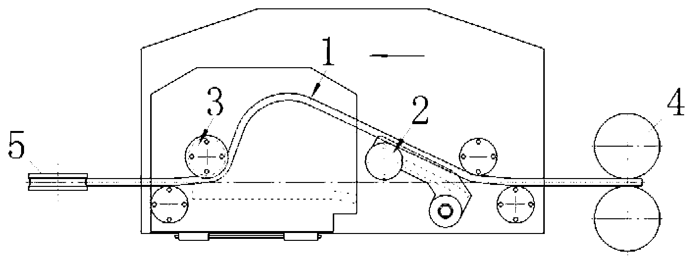
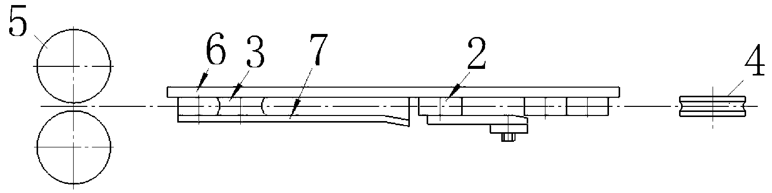
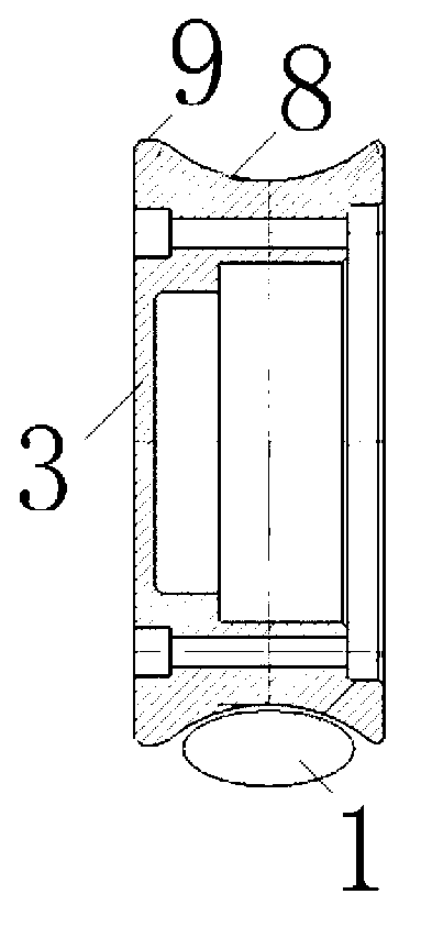
[0017] Such as Figure 1 to Figure 4 As shown, a high-speed wire rod rolling mill vertical loop device, the vertical loop device is located between the upstream rolling mill 4 and the downstream rolling mill 5, and it includes a sheathing roll 2 and a guide roll 3 and loopers located on both sides of the guide roll The side plates, that is, the looper side plate I6 and the looper side plate II7, are provided with a guide groove 8 with a guide centering function on the roller surface of the guide roller 3 . When the rolling piece 1 enters the vertical looper device, the rolling piece moves along the arc track after the sheathing roll 2 sets the rolling piece, and the rolling piece can always run in the looper rolling position through the guide groove 8 to limit the rolling piece. In the middle ...


PUM


Abstract

The invention discloses a vertical loop device for a high-speed wire rod rolling mill. The device is arranged between an upstream rolling mill and a downstream rolling mill, and comprises a loop rising roller, a guide roller, and loop side plates arranged on two sides of the guide roller, wherein a guide slot with a guide centering function is formed in the roller surface of the guide roller. A rolled piece can always operate at the middle position of a loop rolling channel by the guide slot, the rolled piece is prevented from being scratched by the loop side plates, and the product quality is improved; the wire scratching phenomenon is eliminated, the rolling fault time is greatly reduced, and the working efficiency of the rolling mill is improved; and the wear of the loop side plates and a downstream rolling mill inlet guide and protection part is reduced, the service life is prolonged, and the rolling cost is reduced.

Description

technical field [0001] The invention relates to the technical field of rolling equipment, in particular to a vertical looper device for a high-speed wire rod rolling mill. Background technique [0002] The high-speed wire rod pre-finishing mill is composed of four racks of two-roll rolling mills alternately horizontal and vertical. In order to achieve tension-free rolling, a vertical looper device is installed between each two rolling mills to adjust the speed of the upstream rolling mill, so as to ensure the rolling of the front and rear stands. Part volume second flow rate is equal. [0003] The take-up roll and guide roll of the existing vertical looper device are both flat rolls, and the high-speed wire moves in an arc after the take-up roll is set up, because the guide roll cannot guide the rolling piece to the middle position of the vertical looper rolling channel , The looper side plates on both sides of the rolling channel outlet often scratch the surface of the rol...

Claims


Application Information

Patent Timeline
Patent Type & Authority Applications(China)
IPC IPC(8): B21B41/00
Inventor 刘朝彤宋强陈晓明王金来张本练
Owner MAGANG (GROUP) HOLDING CO LTD
Why Eureka
Try Eureka