
Mounting/dismounting device for disc milling cutter

A loading and unloading device and disk milling cutter technology, which is applied in metal processing equipment, metal processing, manufacturing tools, etc., can solve the problems of low loading and unloading efficiency, operator injury, heavy weight, etc., to reduce the difficulty of loading and unloading, improve loading and unloading efficiency, and process Create easy effects

Active Publication Date: 2013-07-03
HANGZHOU BRANCH ZHEJIANG GEELY AUTOMOBILE RES INST +2
View PDF5 Cites 4 Cited by
  • Summary
  • Abstract
  • Description
  • Claims
  • Application Information

AI Technical Summary

Problems solved by technology

Due to the lack of special loading and unloading devices, at present, the loading and unloading of the disc milling cutter is mostly carried out by manually moving the disc milling cutter directly for installation and disassembly.
However, disc milling cutters are often large in diameter and heavy in weight, and the method of manually moving the disc milling cutter for installation, alignment and disassembly has the problems of difficult operation and low loading and unloading efficiency. The blade is also easy to cause injury to the operator, and the installation and unloading of the disc milling cutter also has a large safety hazard

Method used


Image

  • Mounting/dismounting device for disc milling cutter
  • Mounting/dismounting device for disc milling cutter

Examples


Embodiment Construction

[0019] The technical solutions of the present invention will be further specifically described below through the embodiments and in conjunction with the accompanying drawings.

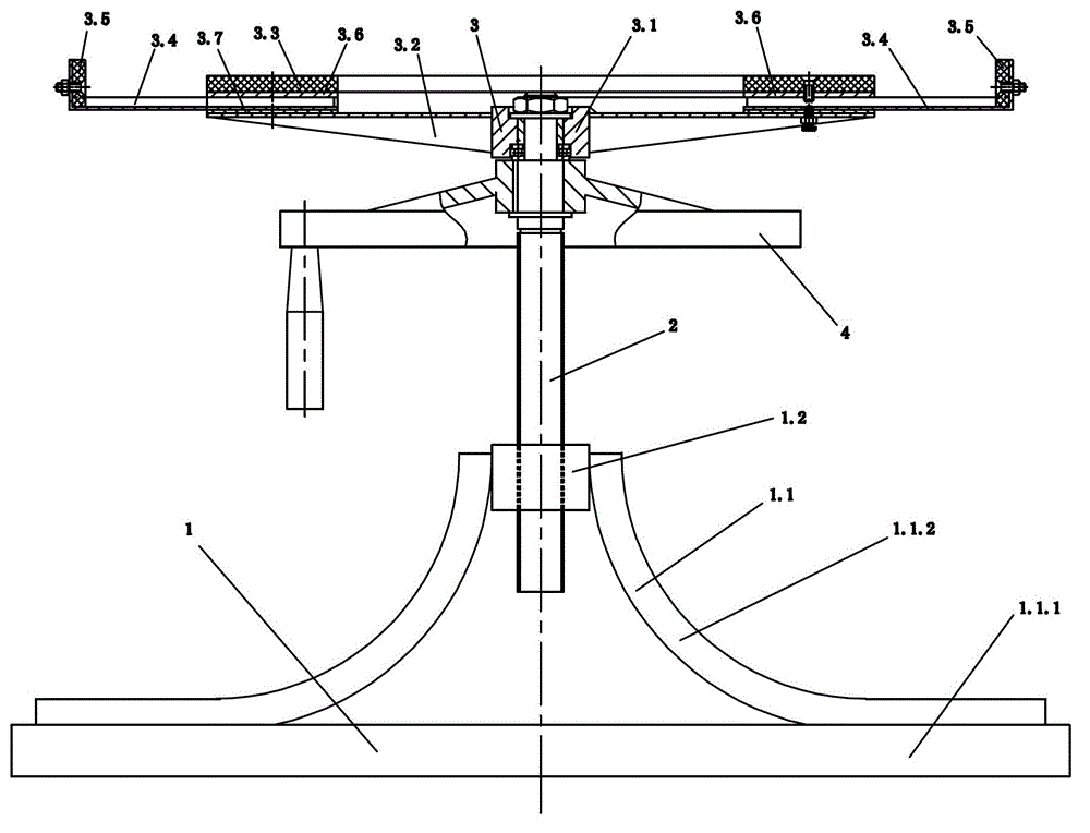
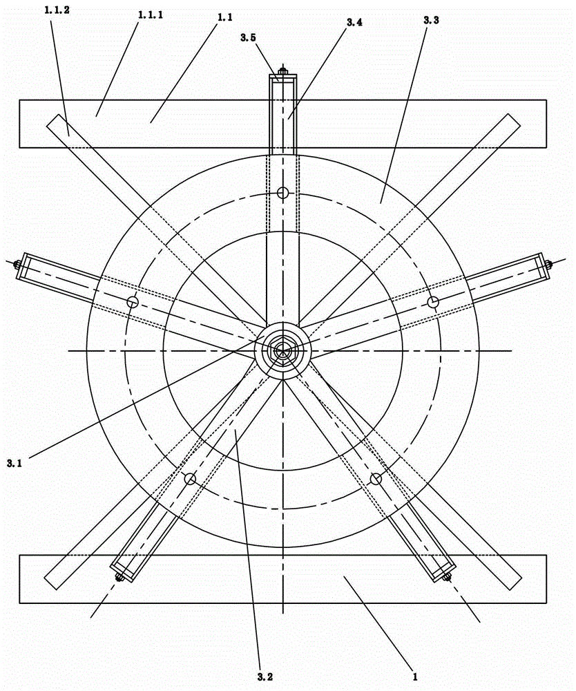
[0020] like figure 1 and figure 2 As shown, the present invention includes a support 1, an elevating shaft 2, a cutter head 3 and a hand wheel 4; 1. A connecting screw block 1.2 with a vertical screw hole is provided on it; the lower end of the lifting shaft 2 is threadedly connected with the connecting screw block 1.2, and the upper end of the lifting shaft 2 is hinged with the cutter head 3; the hand wheel 3 is fixed to the lifting shaft 2 Connected to the bottom of the cutter head 3;

[0021] As a preference, the frame foot 1.1 of this embodiment includes two horizontally opposite feet 1.1.1 and four foot columns 1.1.2, the four foot columns 1.1.2 are symmetrically arranged in pairs, and the four foot columns 1.1.2 The lower ends of each of the four legs 1.1.1 are fixedly connected to one end of...


PUM


Abstract

A mounting / dismounting device for a disc milling cutter comprises a support, a lifting shaft, a cutter supporting disc and a hand wheel, wherein the support comprises a frame foot formed by fixedly connecting a plurality of strip-shaped parts and a connecting threaded block fixed in the center of the upper end of the frame foot and provided with a vertical threaded hole; the lower ends of the cutter supporting disc and the lifting shaft are in threaded connection with the connecting threaded block, and the upper end of the lifting shaft is hinged with the cutter supporting disc; and the hand wheel and the lifting shaft are fixedly connected below the cutter supporting disc. When in use, the mounting / dismounting device for the disc milling cutter is placed on a workbench of a milling machine and used for operation of connecting and dismounting of the disc milling cutter and the milling machine, can lower difficulty in mounting and dismounting the disc milling cutter on the milling machine, facilitates improvement on mounting / dismounting efficiency and safety of the disc milling cutter, and has the advantages of simple structure and convenience in use.

Description

technical field [0001] The invention relates to the field of mechanical processing and manufacturing, in particular to a special loading and unloading device for disc-shaped milling cutters. [0002] Background technique [0003] In the field of machining and manufacturing, plane milling often occurs. If the plane to be machined is large, it is usually processed with a disc milling cutter, so that the flatness of the machined plane can be well guaranteed. Due to the lack of a special loading and unloading device, at present, the loading and unloading of the disc milling cutter mostly adopts the method of manually moving the disc milling cutter directly by hand for installation, alignment and dismounting. However, disc milling cutters are often large in diameter and heavy in weight, and the method of manually moving the disc milling cutter for installation, alignment and disassembly has the problems of difficult operation and low loading and unloading efficiency. The blade...

Claims


Application Information

Patent Timeline
IPC IPC(8): B23P19/00
Inventor 童向荣王振陈启云李慧军由毅赵福全
Owner HANGZHOU BRANCH ZHEJIANG GEELY AUTOMOBILE RES INST
Learn More