Concrete permeability detection device and method
A detection device and permeability technology, applied in measurement devices, permeability/surface area analysis, climate sustainability, etc., can solve problems such as inaccurate test results, achieve convenient and fast operation, convenient test loading and unloading, and ensure accuracy. Effect
- Summary
- Abstract
- Description
- Claims
- Application Information
AI Technical Summary
Problems solved by technology
Method used
Image
Examples
Embodiment 1
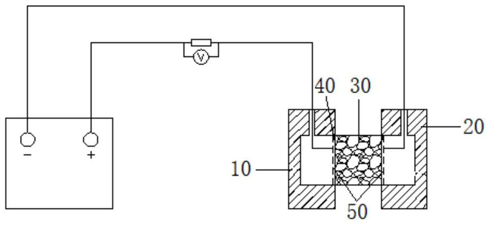
[0056] like Figure 9 As shown, the number of the connecting parts 63 is two, and the two connecting parts 63, the first clamping part 61 and the second clamping part 62 constitute the frame structure of the clamping device 60, and the first test groove 10 is provided with an installation The first clamping part 11 of the clamping device 60 is provided with the second clamping part 21 on which the clamping device 60 is installed in the second test groove 20 . The frame structure can be made of stainless steel. When in use, the stainless steel frame structure is sleeved into the test slot, so that the frame structure is clamped at the first clamping part 11 and the second clamping part 21, the structure is simple, the cost is low, and the weight is light. , Easy to operate.
[0057] like Figure 10 As shown, the first engaging portion 11 is a concave platform on both sides of the first test slot 10, the second engaging portion 21 is a concave platform on both sides of the sec...
Embodiment 2
[0060] like Figure 12 As shown, the difference between the second embodiment and the first embodiment is: the first clamping portion 11 is a groove with the outer end surface of the first test slot 10 located in the longitudinal center, and the second clamping portion 21 is the end face of the second test slot 20 For the groove located in the longitudinal center, a positioning groove 212 is also provided in the middle of the second engaging portion 21 .
[0061] The outer end face of the first test slot 10 is the end face away from the second test slot 20 , and the outer end face of the second test slot 20 is the end face away from the first test slot 10 . The groove is a through groove with a length of 1 cm and a thickness of 0.5 cm symmetrically cut from the longitudinal center of the test groove to both sides, and then a positioning groove 212 is machined in the middle of the back of the second test groove 20. The positioning groove 212 can be circular or rectangular.
[...
Embodiment 3
[0064] like Figure 14 , 15 As shown, the structure of the clamping device 60 in the third embodiment is different from that in the first and second embodiments: the connecting part 63 is one, and one connecting part 63 forms a clamping part with the first clamping part 61 and the second clamping part 62 U-shaped configuration of device 60 .
[0065] The working principle of the clamping device 60 in this embodiment is roughly the same as that in the first and second embodiments, the difference is that the closed frame structure is replaced with a U-shaped baffle machined from a stainless steel plate of a certain thickness. There is no need for additional cutting of the groove, and the clamping and fixing device of this solution has better compatibility and is suitable for the clamping of test grooves of various external dimensions.
[0066] The second clamping part 62 includes a first support 621 , a second support 622 , and a third support 623 connected in sequence, the fi...
PUM
 Abstract
Description
Claims
Application Information
 - R&D
- Intellectual Property
- Life Sciences
- Materials
- Tech Scout
- Unparalleled Data Quality
- Higher Quality Content
- 60% Fewer Hallucinations
Browse by: Latest US Patents, China's latest patents, Technical Efficacy Thesaurus, Application Domain, Technology Topic, Popular Technical Reports.
© 2025 PatSnap. All rights reserved.Legal|Privacy policy|Modern Slavery Act Transparency Statement|Sitemap|About US| Contact US: help@patsnap.com


